Stephenson's Reversing Gear For Locomotives
Description
This section is from the book "Cassell's Cyclopaedia Of Mechanics", by Paul N. Hasluck. Also available from Amazon: Cassell's Cyclopaedia Of Mechanics.
Stephenson's Reversing Gear For Locomotives
The adjoining illustration shows the Stephenson reversing gear. V is the slide valve, and C the crankshaft carrying two eccentrics E and E', with centres as shown. A link L carries a die D connected to the valve rod, which works in a guide S. The hand lever II can be moved over the sector Q, and can be locked in any one of the notches shown. This lever, by means of a balancing system of links, etc., at K, M, v, etc., moves the curved link L. To this link at centres P and P' are connected the eccentrics E and E'. By altering the position of the link either eccentric may be put in gear. For instance, as shown, the valve would receive motion from E', but by moving the handle over to the other side of the sector Q the die block would be at the lower end of the link and E would be in gear. With the handle at the centre of the sector, the die would be at the centre of the link and the valve would receive no motion from the eccentrics, the forward movement of one being partly balanced by the backward movement of the other eccentric. As the eccentrics are not exactly opposite, the valve, in mid gear, opens to lead only.
To reverse the end, it is only necessary to put in gear the eccentric that was previously not in gear.
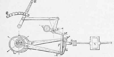
Stephenson's Reversing Gear for Locomotive.
Continue to:
My Books

