


Taking Off Bevels For Rafters
Description
This section is from the book "Cassell's Cyclopaedia Of Mechanics", by Paul N. Hasluck. Also available from Amazon: Cassell's Cyclopaedia Of Mechanics.
Taking Off Bevels For Rafters
Au explanation of how bevels for rafters are taken off the drawing and put on the stuff to be cut is here given. Set out for the bevels as shown at Fig. 1; the bevel at A being for the vertical cut, and that at 15 for the bevel to be applied at the edge of the rafter. The bevels can be set from the drawing as shown at Fig. 1. Fig. 2 shows the bevel B (Fig. 1) applied to the top edge of the rafter, and Fig. 3 shows bevel A (Fig. 1) applied to the side of it. This will perhaps be more clearly understood from the isometric view given at Fig. 1, which shows the application of the bevels. The form of the cut C (Fig. 1) is the bevel for feet of rafters.
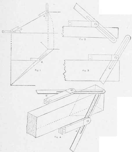
Taking off Bevels for Rafters.
Continue to:


My Books

