Wells System Of Measuring Distances
Description
This section is from the book "Cassell's Cyclopaedia Of Mechanics", by Paul N. Hasluck. Also available from Amazon: Cassell's Cyclopaedia Of Mechanics.
Wells System Of Measuring Distances
The accompanying figures show the Wells -apparatus used by surveyors for judging distance when taking trial levels without chaining the horizontal distances. It may also be used as a check upon chained measurements. The apparatus consistsof a needle point A attached to the diaphragm of any levelling telescope, and movable in a vertical direction so that its distance from the horizontal crosshair or wire may be regulated by the micrometer screw B, the top of which is graduated, as shown in the plan, to serve as a reference in setting the needle point. The index-pointer to this graduated circle is fixed upon the front of the telescope over the eye-piece, as shown in front and side elevation. The needle, which is worked up and down by the micrometer screw B between the limits marked " traverse of needle," travels in the same vertical plane as that in which the cross-hairs are fixed. To set the needle, measure any distance, say 100 ft., upon level ground, set up the level so that the telescope stands over one end of the measured distance, while the staff is held at the other end.
Focus the telescope accurately, and move the needle-point A in the diaphragm by the screw-head B until exactly 1ft. of the staff image is enclosed between the needle-point and the horizontal cross-hair in the diaphragm. In this way a datum distance reading may be obtained, from which other distances of varying lengths can be easily calculated. The divisions upon the top of the screw B (see plan), where the index-pointer touches, should then be noted for future reference.
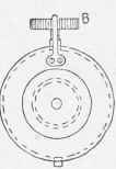
FRONT VIEW.
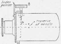
SIDE. ELEVATION.
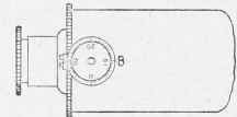
PLAN. Wells System of Measuring Distances.
Continue to:
My Books

