Lever
Description
This section is from the book "The Engineer's And Mechanic's Encyclopaedia", by Luke Hebert. Also available from Amazon: Engineer's And Mechanic's Encyclopaedia.
Lever
One of the mechanic powers, or elements of machinery. It is usually defined an inflexible bar, movable round a fixed point of support, denominated the fulcrum. There are three kinds of levers, distinguished by the relative positions of the power, weight, and fulcrum. In levers of the first kind, the weight is applied at one end, the power that is to move it, at the other, and the fulcrum between them. In Fig. 1, on the next page, which represents a lever of this kind, W is the weight, P the power, and F the fulcrum; while the distances F W and F P represent the arms of the lever. Fig. 2 is an example of a lever of the second kind, in which the fulcrum F is at one end, the power P at the other, and the weight W between them; the arms of the lever are represented by the same letters as before, F W, and F P. The third kind of lever, has its fulcrum F at one end, the weight W at the other, and the power P between them, as in Fig. 3.
The relation between the power and weight is exceedingly simple. Thus, if the forces applied to a straight lever, are weights acting on it perpendicularly to the horizon, the proportion which the power bears to the weight, will be as the distance of the weight from the fulcrum is to the distance of the power from the same point, that is, the power and weight are inversely as their distances from the fulcrum. A general proposition, however, applicable alike to straight and bent levers, and to forces in any direction, may be thus stated. The power and resistance acting on a lever are inversely proportional to the perpendicular lines drawn from the fulcrum to the lines of direction in which the forces act. To render the laws connected with this useful instrument as plain as possible, we shall consider the different cases separately. In Fig. 4, abc represents a lever whose fulcrum is at b, the power is to the weight as the shorter arm a b is to the longer b c. For if the lever be put into motion, the power will describe the arc c d, and the weight, the arc a e, which represent the velocity with which the bodies move. Now as these arcs are proportional to the length of the arms, if we multiply them by quantities which are inversely as the lengths of the arms, we shall produce equal quantities.
Now the lever will remain at rest when the momenta of its arms in opposite directions are equal, and this will occur, as we have shown, when the power and weight are inversely proportional to the lengths of the arms. If the arms are as 1 to 2, as in Fig. 5, a power of 50 lb. will counterbalance a resistance of 100 lb. The same will appear in a lever of the second and third kinds. In Fig. 6, let the longer arm a b be 12 feet, and the shorter a c, 2 feet, then will the power be to the weight as 2 to 12; that is, a power of 50 will balance a weight of 300 lb. If the weight 300 be multiplied by the arm a c - 2, it will give a product of 600, the same as the 50 lb. multiplied by the arm a b = 12. This is constantly the case, that the power multiplied by its perpendicular distance from the fulcrum is equal to the weight multiplied by its distance from the same point. In levers of the third kind, in which the power is nearer to the fulcrum than the weight is, a loss of power is sustained, but this is amply compensated in the increased velocity that is obtained.
In this, as in the other levers, is clearly evidenced that important truth in Mechanics, that in every case in which power is increased velocity must be diminished.
Fig. I.
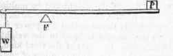
Fig. 2.

Fig. 3.
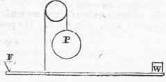
Fig. 4.
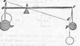
Fig. 5.
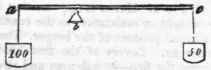
Fig. 6.

In levers of the first kind, the pressure on the fulcrum is equal to the sum of the forces acting upon it, and in the second and third, to the difference between them. Sometimes a number of forces may be applied at once, as in Fig. 7. In this case, equilibrium will obtain, when the products formed by multiplying each weight by its distance from the fulcrum, are equal on each side. When a series of levers are made to act on each other, they constitute a compound lever, as in Fig. 8. The power obtained by this lever is calculated in the same way as the simple lever. Suppose each of the longer arms to be twice as long as the shorter ones, then a weight of 10 lb. suspended to fg, will counterbalance 20 lb. suspended to ef. If, instead of suspending a weight to the arm ef, it be made to act with its force of 20 lb. on the arm e d, it will support a resistance of 40 lb. at e, this 40 lb. acting on b c will sustain 80 lb. suspended to a. Hence it appears that in levers of this description, the power is to the weight or resistance, as the continued product of the shorter arms is to the continued product of the longer. The applications of the levers are exceedingly numerous.
Levers of the first kind may be seen in the use of a poker in stirring the fire - in balances and steelyards - in scissors and snuffers, in which the rivet forms the fulcrum. A crow bar may be used either as a lever of the first or second kind, as in the accompanying sketches. The bent or angular lever may be seen in the action of a hammer in drawing a nail, Fig. 10. The handle of the hammer being the longer arm, and the distance from the nail to the point on which the hammer rests, the shorter arm. Levers of the second kind may be seen in a pair of bellows - in oars used in rowing boats, in the rudder of a ship, nutcrackers, etc. The safety-valves of steam engines are sometimes levers of the second kind. In Fig. 12, b is the power applied at different distances along the arm a b, the steam endeavouring to escape from the boiler is the resistance acting at c. It will easily be apprehended that the greater the distance between a and b, the greater will be the compressing force on the steam. Levers of the third kind may be seen in the human arm, a pair of tongs, shears for sheepsheering.
Other examples might be given, but to those who have considered the instances already adduced, they will be sufficiently obvious.
Fig. 7.

Fig. 8.

Fig. 9.

Continue to:
My Books

