152. The Billet Mill
Description
This section is from the book "An Elementary Outline Of Mechanical Processes", by G. W. Danforth. Also available from Amazon: An elementary outline of mechanical processes.
152. The Billet Mill
Fig. 45 shows a three-high billet mill. Each of the rolls of this mill runs continuously in one direction as shown by the arrows. To allow a bloom (or a small ingot) to be run between the upper and middle rolls, this form of mill is equipped with lifting tables. A section of the roller table about 20 or 30 feet long which lies next to the mill on each side is so hinged that the ends adjacent to the mill can be lifted to the level B in the figure. After the bloom A passes through the mill with the table in the position now shown, the table ends on both sides of the mill are lifted by hydraulic mechanism. The table rollers, are then reversed and the bloom passes back to this side. Both tables are then lowered to the position shown in the figure and the bloom is again passed between the middle and the lower rolls.
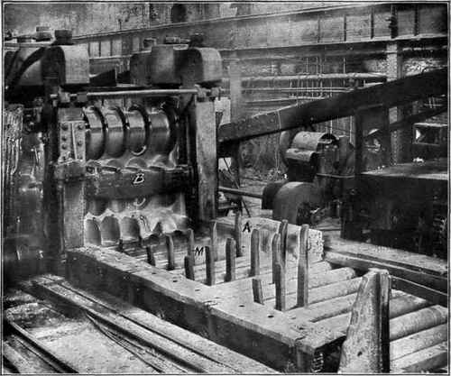
Fig. 45. - Three-High Billet Mill.
The rolls of this mill remain the same distance apart, and the bloom is reduced by being sent through the different passes between the rolls, which are successively smaller along the rolls. The several fingers or prongs M are for the purpose of turning the bloom over and directing it to any pass through the rolls as may be desired. These fingers belong to the manipulator, various types of which are fitted to mills, and are so controlled by hydraulic mechanism that they can be lowered, raised and moved from side to side between the rollers at will.
Continue to:
My Books

