Mechanical Drawing. VI. Original Studies
Description
This section is from the book "Amateur Work Magazine Vol1". Also available from Amazon: Amateur Work.
Mechanical Drawing. VI. Original Studies
Earnest T. Childs.
The subject of sections and section lining has been generally discussed in the last two chapters, and the student needs merely to apply the principles contained therein to obtain satisfactory results. As previously stated, constant application is the price of success, and while the illustrations which are given herewith are good examples for the student, it will be advantageous to go outside and apply these principles on original studies. Let the student take some article which is in daily use, And work up a drawing of it or some of its parts.
For instance, a lawn-mower is familiar to all, but how many know just how it works ? This will make an excellent subject for practice, and by the time the student has made a set of detail drawings and an erection drawing, working from the machine itself, he will have acquired a good fund of experience which could be obtained in no better way. The work of measuring up must necessarily be accomplished first, and this will necessitate a sketch or note book, on account of the impossibility of making a neat drawing when working from a dirty, oily piece of machinery. A lawn-mower is, however, no dirtier than many pieces of machinery which have to be oiled. A sketchbook is preferable to a block, as all sketches may be preserved, and oftentimes an old sketch may save time and trouble for the draughtsman. The sketches should, of course, be made free-hand, and as clear and accurate as possible. Due attention must be paid to the relative sizes, so that the sketch will be in good proportion. In other words, make sketches look as much like the object as possible.
In sketching a gear, it will not be necessary to outline every tooth. Simply show two or three and give all the necessary figures for drawing the teeth in detail, covering the number of teeth by a note. It will be found impossible to keep the sketchbook as clean as a drawing, but neatness adds greatly to the ease of reproducing the work on the drawing. If a lawn-mower is not available, a very interesting subject will be a doorknob and lock. Every one can get one of these, and it will be the best possible practice to work up details of the lock and latch complete. These are merely given as illustrations of what may be done.
The important point which must be borne in mind is that original work and original research will be of more help than any amount of copying. When one is working from an object, he can more readily tell just what is most necessary in a drawing to represent that object. The making of free-hand sketches is an important item, and every draughtsman should make it a point to become proficient along this line, as stated above. Care must be taken to preserve the proportions of the object in the sketch.
The novice will experience a great deal of difficulty in making his first sketches, but a little persistence will soon reward him with more and more success. Really, a thorough knowledge of isometric and perspective drawing is necessary, but these are subjects which are to be taken up later. In making sketches of a piece of mechanism, first take the machine to pieces, and then sketch, piece by piece, from the various parts, makingone, two or three views of each piece, as may be required. These sketches should be made without touching the parts, in order that the sketchbook may be kept as clean as possible. When the sketches are complete in outline, look them over, and fill in the various witness marks and dimension lines which are required. Then measure the pieces, jotting down the figures in their proper places. This method not only gives as a result a neater sketch-book, but it helps in the making of the working drawing. In making sketches, be careful to do no slack work; make them so that any one acquainted with drawing could use them, and do not trust anything to the memory.
There is one class of sections which has not been described in the foregoing chapters, namely, broken sections. If a portion of a symmetrical object is to be shown, as in the piston rod shown in the last chapter, it is customary to show the broken rod in such a manner as to suggest its shape. This is illustrated by the free-hand sketches (see Fig. 17). These illustrations have been drawn free-hand, to show the character of work necessary for free-hand sketching.
When a surface is to be finished, it is sometimes helpful to indicate in some manner on the drawing that this is the case. The customary way of doing this is to mark a letter "f" through the line which shows the surface to he finished, or to write out the word "finish " in full. The former is the more common. In some shops this is entirely omitted, and it will be seen by referring to the detail drawings accompanying that they have no finish marks. This may be accounted for, in the present instance, by the fact that over one thousand engines of this size have been built from these drawings, and the workmen are sufficiently familiar with the work to render this information superfluous. On new work this detail should never be omitted, and it is par-ticulaily essential on drawings from which patterns are to be made, as the pattern-maker has to make a special allowance on work which is to be finished.
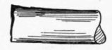
Cylinder
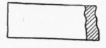
Rectangular Bcir
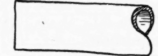
Cylinder
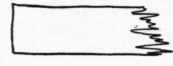
Wood
I Beam
Angle. Iron
Fig. 17.
In making drawings for structural steel work, it is customary to distinguish on the drawing just what part of the work will be done in the shop and what will be done at the time of erection, or " in the field," as it is termed.
The accompanying sketch (Fig. 18) shows one method which is used by one of the largest steel manufacturers in this country - the Pencoyd Iron Works. This shows at a glance whether a rivet is to be driven in the shop or on the ground, and shows the style of head and which side the head is to be on. The standard dimensions of rivets are as follows:
Diameter shank = 1.
Diameter head =1.5 +1/8" Finished heads
Depth head = 0.45 )
Depth head = 0.50 ) Countersunk heads.
Bevel of head = 60 degrees )
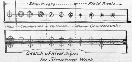
Fig. 18.

Fig. 20.

Approximate allowance in length of shank for forming finished head over and above length of grip :
1/2" = 1".
3/5= 1 1/4"
3/4" = 1 3/4"
7/8 = 1 1/2".
1" = 1 3/8
Approximate allowance in length of shank for forming countersunk head over and above length of grip :
7/8"= 7/8".
1" = 7/8".
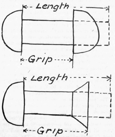
Fig. 19.
For round head add 1/8" to length for each additional inch of grip; for countersunk head add 1/8" to length for each additional two inches (2") of grip. (See Fig. 19.)
The examples for practice in this chapter comprise details necessary before presenting the assembly drawing complete, which will be given in the next chapter. The eccentric strap (Fig. 20) is shown entirely in outline, except that a partial section is shown of the lower half. This was necessary to show the method of holding the Babbitt metal. This will give excellent practice in the use of an irregular curve, and also in the representation of nuts and threads.
Fig. 21, showing the main journal, is a very interesting study. This journal is cast directly to the engine frame, as is indicated by the broken lines; and it is of cast iron, as is indicated by the character of section line. The longitudinal section is shown on the center line, and no special note is necessary. The cross section is broken, the left-hand half being on line AB, and the right-hand half on line CD, thus giving in one drawing three distinct sections.
Continue to:
My Books

