Projection. II. Cubes And Shading
Description
This section is from the book "Amateur Work Magazine Vol1". Also available from Amazon: Amateur Work.
Projection. II. Cubes And Shading
In the projection of solids, the dimensions of length, breadth and thickness, make necessary the use of more than one view for the presentation of an object, that its form and dimensions may be shown in the correct proportions and relation to each other, to enable it to be constructed without other data. It is in this important particular that Mechanical Drawing differs from Perspective or picture drawing.
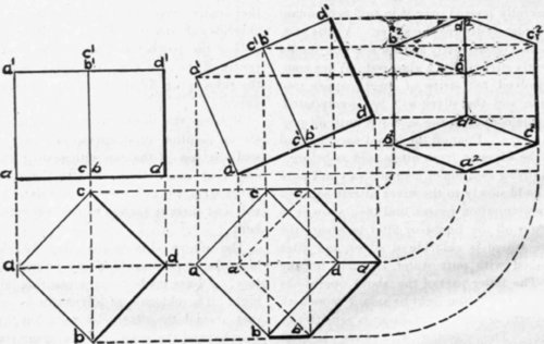
Fig. 11.
Fig. 12.
The first form to be considered is a cube or solid square which we know has six equal sides or squares, each one being parallel to the one opposite. These different surfaces are shown most conveniently for the required purposes by three views known respectively as the Front Elevation, or front view; Side Elevation, or side view (usually the right side), and the Plan, representing a top view; all of these assumed to be from an indefinite distance, great enough to give to the views a plane surface.
The plan is assumed to be of the same plane as that of the paper upon which it is presented, and the other planes or elevations are at right angles with it, but revolved as though on a hinge until brought to the same plane as the plan. If the reader will construct from a piece of cardboard, a figure with three flat surfaces to represent the above named views of a cube, and then lay this figure flat upon the drawing board, the relation these views have to each other will be more easily understood. The joints or hinges between the surfaces of such a figure would represent the lines of intersection of the several planes, which are called the "Axes of Projection."
The three views of a cube so placed that the nearest side was parallel to the front vertical plane would be alike. If it were turned so that the sides were at an angle of 45° from the vertical plane, the Plan and Elevations would be as shown in Fig. 11; the Side Elevation being the same as that of the Front Elevation. Draw the Plan of the cube a b c d. From each of the angles of the Plan, draw perpendiculars of a length, above the intersecting line, equal to the side of the Plan. Draw the top line, a1-d1, completing the elevation. Assume that the cube be inclined until the plane of the base is at an angle of 25° from the horizontal plane, as shown in Fig. 12. The Elevation shown in Fig. 11 is placed so that the plane of the base, a-d, is at the given angle and as the edges are at right angles (90°) to the base, they will be at 60° from the horizontal plane. From the angles of this elevation, draw perpendiculars intersecting them by horizontal lines drawn from the Plan in Fig. 11, and then, drawing the necessary lines to obtain the Plan for the inclined cube. To obtain the Side Elevation, draw horizontal lines to the right from the angles of both the Front Elevation and the Plan. Taking the point where the lines of intersection cross as a centre, describe arcs from the horizontal lines of the Plan and draw vertical projecting lines from these arcs, intersecting the horizontal projecting lines from the Front Elevation. The points of intersection are connected by the lines necessary to complete the Side Elevation.

Fig. 13.
Assume that the cube, in addition to being inclined 25° from the horizontal plane, is inclined 30° from the vertical plane. Draw the Plan with the lines representing the vertical planes at an angle of 30° from the line of intersection, as shown in Fig. 13. Draw perpendiculars from the angles of Plan and horizontals from the Elevation in Fig. 11. The intersections thus obtained give the points necessary to draw the Front Elevation. By continuing the horizontals to the right, and describing arcs from horizontals drawn from the Plan, using the line of intersection as a radius, and drawing verticals from these arcs, the points necessary to the Side Elevation will be obtained.
The reader who is following these studies without the aid of a teacher, may experience some difficulty in clearly and quickly understanding them, but if several additional problems are tried by varying the angles at which the cube is inclined, the experience thus gained will be valuable and interesting.
Shading.
In a chapter of the series on Mechanical Drawing, the use of shade lines was mentioned, and it was there stated that the light was assumed to fall upon the object from the upper left side at an angle of 45°. In applying this rule to projections however, it is desirable to modify this rule to the extent that shade lines are used only on the right hand and lower edges, as will be noted from the illustrations for this chapter. If the rule were arbitrarily adhered to, the determining of whether shade lines were required or not would so frequently require a nicity of decision and the use of so much time in making it, as to make quite desirable the modification above mentioned. If this is done, the use of shading soon becomes a matter of habit. The lettering adopted for this series makes use of the vertical letter for upper planes and italic for the lower ones. All drawings made by the student should be carefully lettered, both for the practice and clearness of the drawing.
Those who use, in the process of intensification, or bromide print toning, the ill smelling ammonium sulphide, will be glad to hear, on the authority of R. Blake Smith in Photogram, that the sodium salt answers the various purposes quite as well, and is almost odorless. The Photogram cautions purchasers to be sure they get the sulphide, and not the more generally used sulphite.
Continue to:
My Books

