Studies In Electricity. XI. Parts Of The Dynamo
Description
This section is from the book "Amateur Work Magazine Vol1". Also available from Amazon: Amateur Work.
Studies In Electricity. XI. Parts Of The Dynamo
As mentioned in previous chapters, the held of a dynamo provides the lines of magnetic force in which the coils of the armature revolves, cutting these lines of force and thus generating an electro-motive force. In the earliest forms of dynamos permanent magnets were used for the field, but these have long been discarded, except in the smallest sizes and for special purposes, such as the magnet ringing, device of the telephone, spark generators for gas engines, and the hand-power dynamo of the laboratory. In these forms of the dynamo the permanent magnet is used, but in the larger forms of direct-current machines the fields are self-excited electro magnets.

Fig. 30.
The designs of the different manufactures differ greatly in form, the aim in all being to secure an easy and short path for the flow of the magnetic lines of force in as compact and cheaply constructed a form as possible. The work to be done also regulates to quite an extent the design of a dynamo. A complete magnetic circuit must be provided to secure a flow of the magneto-motive force (M M F), just as a complete outside circuit is necessary to the flow of the electric current. This is shown in Fig. 30, which is an upright horseshoe type of single circuit bipolar field magnet, the magnetic circuit being shown by the dotted lines.
The Edison dynamos were of this type, but have for many uses been supplanted by other forms, which are mechanically more desirable, such as the form shown in Fig. 31. This has two magnetic circuits, and is also known as "iron-clad," from the fact that the poles are enclosed. This is the popular form for small dynamos, having great mechanical strength and well protected from injury. This general design with two extra poles, one on each side, makes a four pole dynamo, thus introducing the type known as a multipolar dynamo, illustrated by Fig. 32. Large machines are generally of this type, the number and size of poles differing greatly with different manufactures. This type requires less iron and wiring than do the others, weighs less for a given output, and is more easily transported and erected, all of which are of much importance when we consider the immense size of the machines now being used
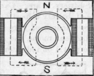
Fig. 31.

Fig. 32.
The reader is advised to inspect as many different dynamos as he conveniently can, and observe carefully how they differ in form and design. In doing this, much incidental information of value will also he acquired.
As explained in the previous chapter, the armature of a dynamo is the part which generates the electric current. There are two forms commonly used, known respectively as the Gramme or ring pattern, and the drum armature. The armatures of all commercial dynamos are of either of these two kinds, or modifications of them. In the Gramme type the core is an iron ring upon which the coils are wound, as illustrated in Fig. 33. The forms for winding and the methods of connecting the coils vary widely, but may be grouped into two classes, known as closed coil, in which the coils are all connected, as shown in Fig. 33, and open coil, in which each coil performs its work entirely independent of the others.

Fig. 33.
The armature core, in all types of armatures, serves not only as a support for the wire coils, but also acts as a conductor for the magnetic lines of force in their passage from pole to pole. It is very essential that they be well adapted to perform this latter function. If made of a single piece of iron, it would, while rotating in the magnetic field, induce currents, known as eddy currents, which not only cause a waste of energy but develop heat, which would be injurious. To avoid this, the cores are made of thin sheets of soft iron, insulated from each other, and so arranged that while still providing a suitable path for the magnetic flux between the poles, no eddy currents are set up.
In the ring armature the core is made of strips of thin iron arranged in concentric rings. In the drum armature the core is made of numerous thin circular discs, insulated from each other usuallv with paper, and having on the circumference a suitable number of slots, as shown in Fig. 34, in which are wound the wire coils. This enables the space between the armature and the poles, known as the air gap, to be only great enough to prevent contact between the two. In the smaller sizes of dynamos the discs are attached directly to the shaft and secured firmly in place, usually by end plates made of brass held by nuts threaded to the shaft. The number, size and shape of the slots cut in the discs for the coils vary widely, and likewise the wiring of the coils. This subject will receive more extended attention when the construction of some particular form of dynamo is presented. In the larger sizes of dynamo the cores of the ring, and the larger sizes of the drum type, are attached to the shaft by what are known as "spiders." They consist of a hub, which is keyed to the shaft, and has arms which are attached to the core by bolts.

Fig. 34.
Continue to:
My Books

