The Wheatstone Bridge
Description
This section is from the book "Amateur Work Magazine Vol1". Also available from Amazon: Amateur Work.
The Wheatstone Bridge
For rapid and accurate comparison of known with unknown resistances of various lengths of wire, lamps, etc., an instrument known as a "Wheatstone bridge " is employed. It was invented by Christie, but has received the name of the more widely known scientist. As it is easily made, and of much value in electrical experimental work, many readers of this magazine will be interested to learn how it is constructed and used.
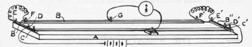
The materials required are : A piece of well-seasoned hard wood, 41" long, 6" wide and 7/8" thick; one piece of brass rod 37" long, 1/2" wide and 3/8" thick, and two similiar pieces 5" long; 10 binding-posts with screw points; a piece of German silver wire, No. 26 gauge, 45" long, and a small piece of brass for a pointer. It is quite important that the wire be of perfectly uniform gauge throughout, and without kinks or nicks.
The illustration shows the arrangement of the pieces of brass and binding-posts. Holes are drilled in the brass pieces large enough for the screw points of the binding-posts. The end brass pieces B' and B" are then carefully located, so that the space between the binding-posts C and C will measure exactly one meter. This in English measure is a trifle less than 393/8". The bindand held in place by three screws, the paper tube being made enough longer to receive it. Care should be taken to see that the battery makes a good contact with the spring G and with the wire connecting with the ring L.
When completed, the outside of the tube may be covered with dark-colored paper or leatherette. This torch is not suitable for continued lighting, but is intended for service requiring light only at intervals. It is a very handy device for use about the house or on the street at night when a light is needed for temporary use. In time, depending upon the extent it is used, the battery will give out, and is then replaced with a new one at a cost of about 30 cents.
ing-posts C and C are then screwed down and the remaining binding-posts placed, thus fastening the brass pieces to the base. A space 1" wide is left between the ends of B and the sides of B' and B".
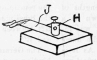
The German silver wire is strung between the binding-posts C and C so that it will be taut, but without tension, so the resistance of the wire will be uniform. To a small block of wood is attached a brass pointer, J, with a binding-post, H. The tip of the pointer should be slightly curved, to give a good contact with the wire, and be kept brightly polished with fine emery-cloth or a file. In moving the pointer always lift it free of the wire, so that the latter will not be scraped or bent.
Under the wire the baseboard may be marked into divisions, preferably those of the metric system. A drawing pen and india ink will be found convenient for this purpose. The ink will not "run" if the wood is sandpapered and then a little talcum powder rubbed over it before marking.
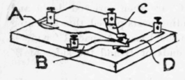
In using this instrument more satisfactory results are secured if a bridge key is used. This is made as follows : On a baseboard 7" long, 5" wide and 3/4 " thick, four binding-posts are attached with a strip of flexible brass leading from each, sothat the free ends of each will rest over one point. These strips are bent so that they will not be in contact except when pressed by the hand. A piece of rubber or cardboard is attached to the upper side of the strip C, so that no connection can be made between the strips B and C. This allows a circuit to be made first through the pieces A-B and then with more pressure through the pieces C-D.
The Wheatstone bridge utilizes the form of a divided circuit in which the current in one branch may be adjusted to equal or "balance " the current of the other branch, and which will be more clearly understood by examining the illustration.
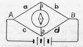
The current flowing through A divides, through the branches a-b and c-d. The potential at any point in the branch a-b will equal the potential at some point in the branch c-d. If these two points (1 and 2) in the branches be connected through a galvanometer, the needle will not be deflected, which would not be the case if the potentials differed.
This instrument is so arranged that in dividing the circuit, known resistances may be utilized to secure a balance with an unknown resistance, thus determining the latter. The known resistances are usually made in the form of coils of insulated wire, of such lengths and size as will make comparisons easy ; such as 1, 2, 3, 5, 10, 25, 50,100 ohms and higher when desired. A table of resistances of copper wire will give the quantity necessary to secure any resistance required. The winding is done in a peculiar manner to avoid self-induction, the wire being doubled upon itself before being wound.
The bridge key is used to send the current through the branches of the bridge before allowing it to pass through the galvanometer; the former, together with the coils, etc., becoming saturated with the current, thus creating no violent deflections in the galvanometer when brought into circuit. The posts A and B are connected to the battery circuit and the posts C and D to the galvanometer circuit. A slight pressure on the knob makes the contact between A and B, and more pressure makes that between C and D. The pointer is moved along the wire and coils are changed until a balance is obtained, the unknown resistance then being easily determined. Much interesting experimental work can be done by the amateur with this instrument in the way of testing the resistance of the wiring of toy motors and of batteries.
Continue to:
My Books

