


Voltmeters. How to Connect and How to Use Them. Continued
Description
This section is from the book "Amateur Work Magazine Vol1". Also available from Amazon: Amateur Work.
Voltmeters. How to Connect and How to Use Them. Continued
The connections of a voltmeter on a switchboard are very simple and easily traced out, but for the purpose of making the matter perfectly clear Fig. 3, which shows the connections in the plainest possible manner, is presented. The generator armature and field are shown at a and to. The rectangle in broken lines indicates the switchboard; the lines P and N are the bus bars: an ammeter is shown at A and a voltmeter at V. The latter is connected with both the bus bars, these taking the place of the wires p and n in Fig. 1. The spaces marked S and cb show the position of the main switch and the circuit-breaker. The distributing circuits are taken off from the two bus bars, generally with a small switch in each circuit, so that it may be disconnected independently of all the others. Such switches are not provided, however, unless required.
Fig. 4 is a diagram which will enable us to make clear several uses to which voltmeters are put, and also the meaning of a number of terms very commonly used. In this diagram, a represents the armature of a generator, and to the field. The wires p and n represent a distributing circuit from which a number of lamps or motors, I, are operated. If a voltmeter is placed at V, and is connected with the points s s'" by means of the wires b b, it will show the electro-motive force, or voltage, acting to force the current from p to line n at the points s s"'. This voltage is the total electro-motive force acting upon the circuit, and it acts to drive a current through the first lamp, I, which is also connected with the points s s"'.
As already stated, the current cannot be driven through wire p from s to s' without the expenditure of some electro-motive force, and hence if we place a second voltmeter at V and connect it with the points s s' by means of the wires c c, the indications upon its dial will show the number of volts required to force the current from s to s' through wire p. The electromotive force acting at the point s to force a current through the lamp I to point s"', or through wire p to point &, is called the potential of the point s. In like manner the electro-motive force acting at point s', to drive the current to point s", is called the potential of the point s'. The voltage indicated by the instrument V' is called the difference of potential between the points s and s', or the fall of potential from s to s'. It is also spoken of as the line drop between s and s', or simply the drop between s and s'.
The difference of potential between the points s and s"', as indicated by the voltmeter V, is referred to as the electro-motive force of the circuit, but the voltage acting between the points s' and s", to force a current through the right-hand lamp I, is generally referred to as the difference of potential between the points s' and s", and it will be equal to the number of volts indicated upon the voltmeter at V".
The current flowing through wire n from a" to s" will absorb a certain amount of voltage, in the same manner as wire p, and this voltage will be indicated upon an instrument placed at V" and connected with the points s" s"', or the difference of potential between these points. As the sum of all the parts cannot be more than the whole, we will find that if the voltage indicated upon the three instruments, V', V", V", are added, they will be equal to the voltage indicated by the instrument V. If we add the voltages indicated by instruments V and V" and deduct it from the reading of V, we will get the volts indicated by V". From this it will be seen that when we speak of line drop, or line loss, we refer to the voltage absorbed in overcoming the resistance of the circuit wires; that is, to the voltages indicated by the instruments V and V' in Fig. 4. The voltage indicated by the voltmeter V cannot be properly referred to as the line drop as it only shows the drop on one side of the circuit, and it must therefore be called the drop in line p, or the drop on one side of the circuit.
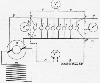
Fig. 4.
The voltage indicated by the instrument V" cannot be spoken of as a drop or fall in potential, for it is the electro-motive force acting in the circuits between the points s' and s", and the active electro-motive force is never referred to as a drop in voltage. Strictly speaking, it would be correct to speak of the indication of voltmeter V as the fall of potential between the points s' and S", but it is not customary to refer to the difference of potential between points on opposite sides of the line in this manner. The word "fall " is used to indicate that the electro-motive force absorbed, or balanced, between two points is lost in overcoming a dead resistance, and not in performing useful work. In some cases, however, this rule is departed from. For example, if we had four or five lamps, of low voltage, connected between the points s' and s", so as to be in series (that is, so that the current would flow through one after the other from the first one to the last one), we would speak of the electro-motive force absorbed by each one of the lamps as the "fall of potential" through the lamp. We would also speak of it as the "difference of potential" between the terminals of each lamp. To avoid making mistakes in the use of terms it is well to remember that the electromotive force lost between two points in the circuit wires, such as s s', can be referred to as the drop or fall of potential between these points, or we can call it the difference of potential between the two points; but the electro-motive force acting between opposite sides of the circuit, to perform useful work, must be spoken of as a difference of potential or as the electro-motive force, or voltage, acting between these points.
Continue to:


My Books

