A Lantern Slide Holder
Description
This section is from the book "Amateur Work Magazine Vol3". Also available from Amazon: Amateur Work.
A Lantern Slide Holder
E. E. Messenger
The lantern slide holder here described presents several advantages over any other which I have ever seen. It is compact, easily worked, and all slide are, when in position, in exact focus, which is not the case with holders having parallel ways, as with the latter either one or both slides must be slightly out of focus. With this holder the slide is carried in the front groove to the opening, then carried back into the back groove, where it remains during exposure, then withdrawn by the back groove.
The material required to make it consist of the wood from two large cigar boxes (250 size), some strip brass about 3/32 thick and 1/4" wide, a piece of 1/8" round brass wire 4" long and three pieces of 1/16" steel wire 2 1/2" long; also brass screws and small wire nails. Side and end views of the frame are shown in Fig. 1. Two sides are cut to the shape and dimensions shown, with openings where the slide is opposite the condensers. The opening in the side nearest the objective is 1/8" larger on the vertical dimension than the side nearest the condenser, 1/16" more at both top and bottom being cut out to allow for the arms a of the transferring device shown in Fig. 4. The right inner edge of the opening on the side nearest the objective is also thinned with a gouge or file to allow for the rod p, Fig. 4.
The top piece of the frame is a strip • of wood 9" long, 5/8 wide and 1/8", or a little over, thick. To the inner right end of this is riveted an L shaped piece of brassb 3 1/2" long, made by bending a piece of thin strip brass 5/8" wide. This is shown at the top of the end view, Fig. 1. A piece of 2-point brass printers rule, can be used, and can be obtained at any printer's office. At the same time get a piece of 8-point brass rule 12" long, from which to make the carrier to be described later. Two small pieces of brass 1/16" thick are also needed for bearings for the rod p, Fig. 4, and are 7/8" long, 1/2" wide. Holes centering 1/8" from the end, and 1/16" diameter are drilled in these pieces, also holes in each corner for small brass nails, and when the frame is put together they are nailed to the top and bottom pieces in slots cut to receive them, so that the centre of the large hole will be exactly 3 15/16" from the right end. Two strips of wood of same dimentions as the top piece are required for the bottom, which is double, the inner one being set 1/8" away from the other to allow the lower arm of the carrier to slide easily between them. Holes are bored 3 15/16" from the right end and near the front edge for rod p, and a space cut out as shown in Fig. 1, around these holes to allow space for the arm b, Fig. 4. Two strips of wood 1/8" x 3/16" are glued between the outer edges of these two bottom pieces, the one on the objective side extending the whole length of the frame, and the one on the condensers side only 3 1/2" from the right end. This last piece is not put in until the final putting together.
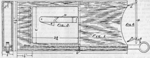

The carrier, as shown in Fig. 2, is next to be made ; three pieces of brass 1/4" wide, \" thick, one 9 3/8" long, another 9 5/8" long, and one 4 3/8" long are needed. The short piece is bent to a 7/8" circle with two arms 3./4" long, to form the pull. If hard brass is. used, it must be annealed by putting in a fire, heating to a red heat and slowly cooled. The upper arm made from the piece 9 3/8" long, has the left end cut down to a width of a little over 1/8" wide for a length of 4 1/2" on the inner end. A boss, s 1/8" wide and 3/4" long is brazed on to the front edge as shown in the top view, Fig. 2. A slot is then cut with a hack saw in the end as shown in the side view, Fig. 2 for the tongue t, and enlarged view of which is shown in Fig. 3. This slot is cut 5/8 " deep from both sides to leave a V shaped projection.
A spring r about 1" long, and 1/8" wide made" of thin spring steel, to be obtained of any jeweller, is then riveted in a recess filed in the front edge of the arm so that the end will press on the edge of the tongue t, causing it to project as shown in Fig. 3. The tongue is filed up from a piece of thin brass, to the shape shown in Fig. 3, holes drilled and a riveted bearing made at the outer end.
The lower arm has at the end a hook shaped projection which is brazed on, as shown in the top view, Fig. 2. When the arms are completed they and the pull are brazed and riveted together. The transferring device, shown in Fig .4, is next to be made. In a piece of round brass rod 1/8" diameter and 4 1/8" long, drill two 1/16" holes in line, one 1/2" from the top end, the other 9/16" from the bottom side. Drill another hole 5/16" from the bottom end at right angles to the other two holes. The two arms a, Fig. 4, are made of steel wire 2 5/16" long, and full 1/16 diameter. The arm b is £" long, with a little over 1/8" on the end turned down as shown in Fig. 4.
After making an end piece of wood 3 13/16" long, 5/8" wide and 3/16" thick, the frame can be put together. It can be nailed with small brass nails, but wood screws are preferable, allowing repairs to be made more easily, but the heads must be countersunk, and holes drilled to avoid splitting the wood. First fasten the top end and side pieces together, following with the inner bottom piece, after putting in position the transferring device. Then put in the carrier, the two wooden strip on either side of the lower arm of carrier and then the outer bottom piece. Put in only a few screws at first and try the carrier to see that it does not bind anywhere. A piece of wood 1/2" long to serve as a stop, is then put between the two sides 1/8" to the left of the opening. One or two coats of shellac varnish will give a good finish to the wood and the brass can be laquered if desired.
To operate, pull out the carrier, put a slide in the space in front of the upper arm, then push on the carrier; the boss, s pushes the slide in till it meets the wooden stop. Then pull out the carrier again; at nearly the end of this movement the catch at the end of the under arm engages with the arm b, causing the arms a, to press against the front of the slide, moving it to the space at the back of the opening. Another slide is then put in, moved forward as before, in front of the one now there; the tongue t is pressed back as it passes the slide first put in until beyond it, when it again projects, and upon pulling out the carrier brings out the first slide, allowing the second slide to be transferred to the space just vacated by the first slide. It will be noted that each slide, during exposure, is in the one space for which the lantern has been accurately focused.
Continue to:
My Books

