A Model Steamboat. III. The Boiler
Description
This section is from the book "Amateur Work Magazine Vol3". Also available from Amazon: Amateur Work.
A Model Steamboat. III. The Boiler
Carl H. Clark
The boiler here described is of the type known as the Scotch cylinder. The shell is 6" diameter and 8" long. It is rolled up from a sheet of copper 8" wide, 19 1/4" long and 3-32" thick. It is to be rolled up exactly circular and riveted together with a lap of 7/8". The rivets should be in a double row and zig-zag spaced. They should be of copper 5-32" diameter, with round heads and should be spaced quite closely together. The riveting must be carefully done, and then riveted and worked up into as much of a head as possible, to draw the ends of the sheet tightly together. As this riveting is a matter requiring some skill it will be well for the amateur to sweat a layer of solder along edge of the joint both inside and outside after riveting to insure thickness.
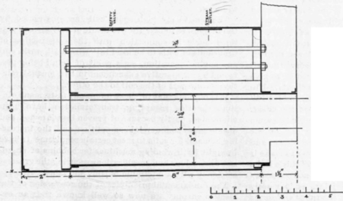
It may be possible to procure a piece of seamless drawn copper or brass pipe of the required diameter and about 5-64" thick. Brazed pipe must not be used as it is not strong enough. The openings in the shell are, one for the safety valve and one for the steam outlet. A reinforcing piece 1-16" thick should be riveted on the shell under each."The holes are to be drilled later. The furnace is a tube 3" diameter, 1-16" thick and 9 1/2" long, with its outer end cut away as shown. Seamless drawn tube must be used for this also.
The heads are 7-64" thick, with the outer .edge flanged to fit inside the shell and a flanged hole to fit over the furnace. About 8/4" should be allowed for flanging and it is accomplished by cutting out a circle of hard wood of the size of the inside of the flange, laying the blank upon it and hammering the edge lightly all around. The effect of this hammering will finally be to shrink the metal and form the flange. The flanged hole is formed in the same manner by hammering the edge over into a smooth round hole. The edges of the flange are then trimmed off to \" wide. This flanging is a nice piece of work and requires much care and patience. The flanges must be round and at right angles to the surface of the plate in order not to warp the shell when riveted together. The front head should have reinforcing plates at the points shown, for the gauge glass, and below the furnace as shown by the dotted circle about 3/4 " diameter. There are 7 tubes on each side, 9-16" outside diameter, for which the holes should be now drilled; they should be spaced alike on each head. The holes in the back head should be a trifle smaller than the tube and those in the front head a trifle larger than it; 3-16" holes for the stays are also to be drilled as shown. They should divide up the space between the tubes and shell so that each will bear as near as possible its share of the load produced by the steam pressure on the front head.

In setting up the boiler, the front head is first inserted and riveted in place. The position of the joint in the shell in regard to the furnace should be noted; and the head placed accordingly. The furnace is next adjusted to the opening in the back head and riveted up. The back head and furnace are then inserted from the back, the furnace projecting through the front head the proper amount. The furnace mouth is next riveted and lastly the back head. The rivets for this purpose are about 5-32" diameter, and are spaced about 5-8" on centres in a single vow. The holes should be drilled through both pieces at the same time to be sure of a good bearing, and care must be taken that no chips or riling are between the bearing surfaces to prevent a good bearing.
As the foundation of these joints, to be perfectly steam tight, is a very nice piece of work, it may be well for the amateur to solder all the joints to insure that they shall be tight. It must be borne in mind that no dependence is to be placed upon the solder for strength as this must be supplied by the rivets. The tubes are 9-16" outside diameter, about 1-32" thick, and long enough to extend from outside to outside of heads, and leave about 1/8" on each end for heading over. The back end of the tube is to be filed slightly until it just enters the hole in the back head, and the front end of the tube is to be expanded somewhat by driving in a taper plug until it is a close fit for the hole in the front head. The tubes will pass easily through the hole in the front head, and are driven up to a good bearing making a tight joint with both heads. With a ball pine hammer the projecting end of the tube is now headed over. The ends of the tubes are cleaned and a ring of solder sweated into the corner around the ends of each tube to insure tightness.
The stays are 3-16" diameter, spaced as shown. If possible the ends of the stay, which are threaded, should be upset so as to make the diameter at the bottom of the thread 3-16" and thus preserve the full strength of the rod. The nuts are screwed on to give a slight pressure without distorting the sheets. Under each nut a round washer i" diameter and 1-16" thick is to be placed to further support the sheet. All the stays should have as near as possible the same tension. After they are adjusted the end of the thread projecting through the nut is riveted over and solder sweated around the nut and washer to make it tight. The back sheet is of brass 1-16" thick and a loose fit for the back of the shell. It is not necessary that this should make a tight joint, as it merely guides the flame around through the tubes and forms a combustion chamber. It is held in place by eight angle lugs screwed to it and riveted to the shell. The inside surface of the back sheet is to be covered with asbestos, as any heat passing through this sheet is a loss. This sheet should be so fastened in place as to be removablewh, en desired, to repair leaks or for other purposes.
The up take, or smoke box leading to the funnel is formed of thin iron or brass sheets of the shape shown to fit over the ends of the tubes, and rest on the projecting end of the furnace tube. The upper end must be worked into the round of the funnel which is about 1 1/2" in diameter. The front is held by a small angle fastened to the top of the furnace. It should be removable to get at the tube ends. When the boiler is complete it should be tested. A hole should be drilled in position for the steam outlet and connection made to a small force pump. The boiler is filled with water, and pressure is put upon it with the pump. Any leak will be seen by the water coming out. In place of a force pump, a bicycle pump can be used if desired.
The boiler is designed to carry up to 50 lbs. per sq. inch, and should be tested to 75 lbs. per sq. inch. The boiler is to be supported in the boat by two saddles curved on the upper side to fit the boiler and on the lower side to fit the hull. The various fittings, safety valve pump, etc., will be described in the next issue.
Continue to:
My Books

