


Cutting Tools For Planer Or Lathe. Continued
Description
This section is from the book "Amateur Work Magazine Vol3". Also available from Amazon: Amateur Work.
Cutting Tools For Planer Or Lathe. Continued
Referring to Fig. 2, we will take up the rake and clearance of lathe diamond point tools. The angle or clearance, sometimes called the angle of relief, as indicated here, is about 7°, and sometimes runs to 10° more or less; enough for a safe working angle. Really, the only reason for so much clearance is to avoid rubbing against the cut surface, thereby causing unnecessary frictional resistance to the motion of the lathe. Our efforts should be directed towards finding the angle that will give the least force required for cutting, combined with endurance of tool edge.
While the power required to cut is increased greatly by dullness of the cutting edge, we must avoid the wood chisel edge because time lost in constantly removing the tool for grinding purposes eats up the profit. In Fig. 9 are illustrated two extreme cases ; that on the left, too great top rake and the other without any. The one will do good work for a few minutes, provided the cut is not too heavy, but the wear of the edge is so great that the angle would soon become blunt and it would be very much better to have no top rake at all. On the other hand, the cutting wedge, as I will call the tool ends on the right, is too blunt to do good, clean work, and from the position in which it is set, the chip will come off nearly straight and in small pieces. The happy medium between the two is indicated in Fig. 10.
Side rake means the angle at which the top is ground either to the right or left side. A tool ground for a traversing motion toward the left-hand, cannot be used with a motion toward the right. Therefore side rake is designated right-hand or left-hand, the former being that which has its cutting edge on the right side and the latter on the left side. As the side rake is increased the power to drive it on its traversing direction becomes less as it tends to screw its way along.
Fig. 11 illustrates an important point in setting the tool. The further the cutting edge is from the base, or support, the greater will be the spring. Where this spring is possible the point is drawn into the work as indicated by the dotted line, and furthermore, will produce irregularly shaped work due to the variation in the resistance of cut at points where the tool digs in. This in- , dicates the value of short leverage.
In Continental shops, and especially in England, it has become a recognized principle that the top of cutting edge of tool should not be higher than the top of the support and to obtain its top rake the tool is hollowed out by grinding. Sir Joseph Whitworth designed his lathes so that the tool set on the centre of the work, and any vertical pressure deflected the tool away from the work, as shown in Fig. 12.
Next in importance to the leverage of the tool is the angle at which it is set in relation to the work. Referring now to Fig 6, the tool is shown at right angles to the work and the cutting pressure tends to force the tool around to the right, away from the work, in the direction of the arrow, instead of causing it to dig into the work. If the tool were set as shown in the dotted position it will readily be seen than any slipping or deflection would carry it into the cut.
The third point to be observed in regard to setting the tool is its height relative to the lathe centres. Fig. 13 illustrates this. Tool No. 1 is set below the centre and the dotted line, drawn tangent to the point of the tool on the periphery of the circle, indicates the direction in which the cutting force is applied. The top or cutting surface of the tool forms an angle of 90° with this line. The stock is thus merely crowded off by the tool and there is no cutting or wedge action but still not what it should have. The top tool, No. 3, gives us the best cutting wedge and will do maximum work with minimum resistance.
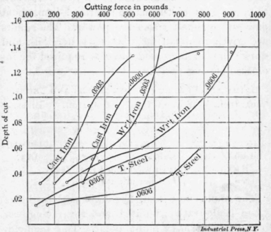
Chart showing: Cutting: Force.
From the foregoing it is clear that the lathe tool will do the best work with combination of top and side rake, when caught very short, at right angles to the work, and when set above the centre. This will lead to economy.
Now a point about grinding: The diamond point tool should be ground only on the top, and the angles on the sides should never be touched, and there will be no danger then that you will destroy the economic value of the tool. Many mechanics burn the cutting edges of the tool in grinding, by simple carelessness, which makes the edge softer than the metal it is supposed to cut. My references thus far have been confined entirely to the solid tools, most commonly used. But there are many improved tool holders in use, designed for self-hardening steel which is not affected by burning in the hands of incompetent mechanics, either in grinding or through of knowledge of the proper cutting speeds. These holders support the steel in such a position as to give the proper front and side clearance and the rake is determined by the grinding.
Following is a table of finishing speeds and feeds for different metals for tools of ordinary tool steel. In roughing the axiom is slow speed and quick feed ; finishing high speed and fine feed From this table I should deduct 25 per cent. for roughing speed, making 18, 24, 28 and 83. Experiments on cutting tools made in the shops of R. H. Smith, London, England, and verified by the author, show that machine steel requires from two to two and one-half times the power for cutting, as does cast-iron, and wrough-iron, about one and one-half times the power. The results are given in detail in the chart herewith and show that an increased force is required for increased cutting speed.
Lathe and Planer Cutting Speeds and Feeds.
Tool Steel. | Wrought Iron Machine Steel. | Cast Iron. | Brass. | ||||
S | F | S | F | S | F | S | F |
24 | 25 | 32 | 25 | 38 | 22 | 110 | 20 |
Lub. | Lub. | Dry. | Dry. | ||||
F = Number of revolutions to 1 inch feed. S = ,, ,, feet per minute.
The round nose tool, Fig. 5, is used for brass when made rather pointed and for facing cast iron when it has a blunt point. The tendency with brass, which is very soft, would be to pull a hooked tool into the work. The side tool should always be set with the point leading slightly, but remembering that it is not the point but the side of the tool that is to do the cutting. This tool should be set on the centre, as indicated in Fig. 14. Fig. 15 shows the necessity for facing up work with the side tool before turning ; otherwise the centre will give more support to one side of the work than the other, and the pressure of the tool used later for turning will be likely to produce a crushing of the metal at the centre, on the side of the least support.
The centering tool should be ground like a twist drill and placed with its cutting point directly at the centre of the work and used to obtain an accurate centre for starting a drill. Much carelessness is exhibited in the use of the thread cutting tools not so much in grinding as in setting. It should be set so that the cutting edges are directly on the line of lathe centres and of course, at right angles to it. The economical way to use this tool is to rough out the thread with a heavy cut and then regrind the top face until again sharp and then finish with a light cut. No matter how carefully a thread tool is used, the sharp point will wear rapidly.
Referring to Fig. 16, we come to the cutting-off tool, the last of the lathe tools shown in Fig. 5. The upper view shows the action of the tool and the two lower views indicate how good and poor results may be obtained through grinding. This tool has side clearance, right and left, and should be ground slightly concave on its top face. Its point should be on a level with the centre of the work.
In Fig. 17, are indicated several of the commoner types of boring tools. The vertical pressure on boring tools is very constant (Fig. 18). and when the tool starts to cut, the depression or spring downward remains very nearly constant throughout its entire cut, and so does not vitally affect accuracy. The tool wears as it advances, however, and this tends to produce a conical hole. Lathes are adjusted, also, so that in no case will they bore a hole larger at the back than at the front, and in making this adjustment the tendency is to have the lathe so it will bore very slightly smaller at the back; another reason why bored holes are frequently a little tapering.
Continue to:


My Books

