


Wireless Telegraph Apparatus
Description
This section is from the book "Amateur Work Magazine Vol3". Also available from Amazon: Amateur Work.
Wireless Telegraph Apparatus
Howard W. Rice
Appreciating the interest taken in electrical subjeots by the readers of Amatuer Work, especially in relation to signalling through space by means of high potential oscillations, the writer, whose working hours during the past three years have been devoted to the designing of apparatus for the highest of induced voltages, takes pleasure in contributing a few personal observations bearing directly upon the sending and receiving ends of experimental wireless stations, such as an amateur would use in connection with a spark coil of moderate size at the sending end.

Without committing myself to any one of several good systems now on the market, one cannot but be in sympathy with the sending equipments that in personal tests have shown up the best. For example, some wireless electricians now in the employ of private and governmental institutions favor one "disperser" because of the noiseless operation, yet equally well posted men would prefer results attending the racket of more vigorous oscillations at the spark gap.
Let us consider in this article that the amateur possesses an induction coil giving about an inch spark or over when operated by a few cells of battery. The spark gap is made of two brass pieces shaped as in Fig. 1 and separated less than 1/8 of an inch.
Fig. 2 shows the transmitting circuit, A being a Leyden jar constructed of a pint battery jar coated inside and out in the usual way with tin foil. The circuit, X, as marked by heavy lines, consists of a bundle of soft iron wires, 6 in. long and £ in. in diameter, on which is wound the entire length, two layers of No. 12 copper wire, heavily insulated with three or more coatings of cotton thread and the layers separated by a layer of thin mica. Over this primary is wound two more layers of mica and five layers of No. 16 cotton covered wire, each layer being separated by a layer of mica, and the wire wound not too snugly together in turns. This coil is to convert the waves that oscilate at the spark gap to a still higher intensity, and the entire windings must be kept in a jar filled with parafine or similar insulating oil.

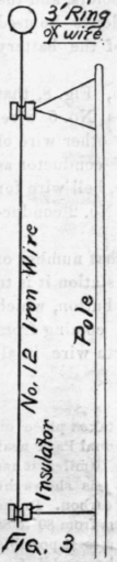
One terminal of the coil con nects with the aerial and the other with the ground plate. This ground plate may be a coil of wire or a sheet of metal, but must be buried where the earth is con stantly moist or wet. The aerial must be insulated and suspended, as in Fig. 3.
The receiving circuit is similar to one used in a very successful type of apparatus, and worthy of following in the construction of apparatus for home experiment.
The coil, which is in the circuit with the receiving aerial, is constructed with an iron wire core § in. diameter and 9 in. long. The primary is two layers of D. C. C.
No. 18 copper wire, insulated with one turn of paper between layers, and four turns of paper between primary and secondary. The secondary consists of six ayers of 36 D. C. C. wire separated by one sheet of thin paper between each layer. This coil may also be immersed in oil.
The coherer herewith illustrated, Fig. 4, is intended for use with a telephone receiver and not with a relay and sounder circuit. As many readers would prefer to experiment with different types of coherers, several types will be illustrated in another article. This type, however, will give excellent results.

The spring is a flexible clock spring, bent in the form of a hoop three inches in diameter. A is a block of polished carbon, B is a metal support, € is a flat disc of aluminum. Between the two are placed three polished steel balls such as are used in bicycle bearings. The pressure of the spring keeps the balls in place. This coherer, if properly constructed, responds in buzzes, and the length of the buzz is regulated by the contact made at the sounding key. It has operated three miles with perfect success. Doubtless much greater distance can be covered under suitable conditions of ground and aerial.
The foregoing set commends itself because of its simplicity of construction and is worthy the attention of all amateurs.
More opportunities for the alternator follow in the wake of the steam turbine. Power says that a curious side issue from the increasing use of steam dynamos is that the dynamo with its commutator is being discredited, whereas, an alternator is, if anything, easier to design for high speed than it is for low speed. Many engineers contend that the commutator is quite impossible for large steam turbines, and it appears that if direct current is required from a large power station in which steam turbines are employed, it is necessary, or at any rate advisable, to instal turbo-alternators and rotary converters. The alternators would be wound for low voltage to avoid the step-down transformers.
Continue to:


My Books

