Electrical Window Display
Description
This section is from the book "Amateur Work Magazine Vol4". Also available from Amazon: Amateur Work.
Electrical Window Display
Oscar N. Dame.
A novel electrical display, something out of the ordinary, will attract more attention than any other device. The following illustration shows an attraction which is easily made and well worth the short time required for its construction. The principle of this device is the see-saw, in which a suspended pendulum of iron acts as an armature and an electrical conductor as well. The horizontal beam must be considerably longer than the pendulum, even longer in proportion than shown in the illustration, so that a good tilting movement may be secured with a minimum of pendulum swing, for it will be seen that the play of the armature between the magnet poles is less than one quarter of an inch.
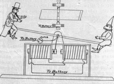
The beam is constructed of a strip of wood 1/8 in. thick and 3/4 in. wide and is evenly balanced on the support as shown in Fig. 1, by means of a small pin-brad, soldered to it. If obtainable, the staff of the balance wheel of an old alarm clock and the two bearings for same make just the thing for this part, as it permits of close adjustment. The pendulum, made from a piece of watch spring, is also soldered to the staff or brad, and bears at its lower end a disc or washer of iron of sufficient weight to counterbalance the tilt-bar. This disc acts as the armature to the magnets.
It will be seen by the illustration that each side of the armature has a contact point of silver or platinum wire, and the attracting pole of each magnet is also tipped with a contact point of the same material.
The wiring diagram of this device must be closely studied to avoid mistakes. Each electro-magnet consists of a 1/2 in. core of iron 2 in. long, wound with 16 layers of No. 20 s. c. magnet wire. The ends of the cores project out from the winding 1/4 in. The battery used is two cells of dry for occasional use, or three cells of gravity for window display. It will be seen by the diagram that one side of the battery is connected to the pendulum support. Then one end of one magnet winding is connected to the iron core of the other magnet. This occurs on both magnets. The other free ends of the magnet windings are connected together and to the other side of the battery.
All of this apparatus and wiring is intended to be covered from view by a box of wood, such as a cigar box, so that only the tilt bar and its support and the upper part of the pendulum are visible to the observer. One puppet should be a clown and the second a Rube. One puppet should also be a trifle heavier than the other, so that the tilt will not balance horizontally, in which case it would not make contact below on the armature. A switch should be placed in the battery circuit.
When the battery is thrown on, the circuit is completed through the pendulum, one core to the opposite magnet winding, back to the battery again. This puts the pendulum armature against the opposite magnet by magnetic attraction, and in contact electrically with the core of that magnet, thereby completing another circuit through core to the winding of the opposite magnet and back to the battery again.
In building this device, remember to reduce the pendulum length as much as posiible. Make the puppets of light wood or paper. Make the tilt arm long in proportion to the length of pendulum, and have the play of the armature between the magnet poles only suffi-cient to give a correct tilt to the tilt arm or bar. Paint everything in bright colors. A change of puppets will give additional interest.
Continue to:
My Books

