Tool Making For Amateurs. Continued
Description
This section is from the book "Amateur Work Magazine Vol4". Also available from Amazon: Amateur Work.
Tool Making For Amateurs. Continued
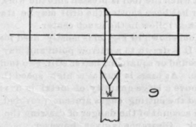
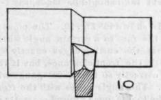
In Fig. 9 is shown the top view or plan of a diamond point tool working into a cut. This tool is given both top and side rake as shown in Fig. 10, which is a view looking along the stock from the tool post, the stock having been broken away. This also shows the side clearance necessary to enable the tool to advance along the piece being turned.
It is evident then, that in order to make a tool cut easily and reduce the work done by the lathe, the tools should be given top rake when cutting in a radial direction, and side rake, or both, when cutting longitudinally. Also that clearance should be provided both in front and on the sides when the tool is used either for radial cuts, as in a cutting off tool, or on the side, as in a diamond point or side tool. The angle of clearance may vary from 3° to 5°, seldom more. The angle of rake depends upon the quality of metal to be worked, the softer metals, such as lead, babbitt, brass and copper being turned with tools having little, if any, top or side rake, while the tools for iron. steel or cast iron will be provided with a rake varying from 3° to 10° as experience dictates. There can be no set rule for this angle, owing to the varying character of the materials being worked.
Fig. 11 shows the diamond point tool which is, perhaps, used to a greater extent than any other single tool. Its chief work is that of taking a roughing cut, and for this particular work it cannot be equalled. It cannot work up to a shoulder, however, without being set at an angle in the post, and for this reason the right hand diamond pointis sometimes provided. They are both given top and side rake, as well as front and side clearance.
In Figs. 13, 14,15 and 16 are shown the right and left hand side tools, both straight and bent. These are used for finishing the ends of cylindrical pieces and flat surfaces generally that are faced in the lathe. As it often occurs that the straight tool will not conveniently reach the center of the work without bringing the tool post in contact with the work, the side tools are provided for such emergencies. They are given considerable side clearance and the top rake is at least 10°. This gives them a very keen edge that can be honed to render the finished surface perfectly smooth and free from scores or scratches. The work that a well sharpened tool will do when properly set is remarkable. The extreme point should be relieved slightly so that it will not leave a line on the surface, as a sharp point will sometimes do. No great amount of stock is to be removed with these tools; use a diamond point for that work and finish with the side tool.
The half-diamond point shown in Fig. 17 is in reality a simple form lying between the side tool and the diamond point, and is used principally for cutting to a square shoulder.
In Fig. 18 is shown a cutting-off tool whose purpose is the cutting off of cylindrical pieces in the lathe. It is made deep under the cutting edge to give it the necessary support, while the extreme point is the widest part, the sides being relieved so that the tool will not bind in the groove. Owing to the confined cutting area it is not practicable to give this tool very much top rake, as the cutting edge is decidedly weakened thereby and likely to be broken off. On the other hand, if the edge is left perfectly square it requires considerable work to push it. into the metal, and the piece will generally break off before rhe cut is finished. This can be obviated by making the cutting edge very narrow. The writer uses a tool slightly less than 1-16 in. wide and 1 in. deep for short cuts, say up to 1/2 in., and for larger pieces up to 2 in., a tool about 3-32 in. wide, with a groove round in the facing edge which breaks the chip into two thin strings which do not bind in this groove and relieve the tool of any great strain. This tool never shows any tendency to run to either side. The thinner the tool the less power required to drive the lathe.
Fig. 19 shows the round nose or filleting tool. Its principal use is for rounding fillets in corners. Several tools of different radii should be made, say 1-16 3/8, 3-16 and 1/4 in.
The thread tool is shown in Fig. 20. The point is made by grinding the face to a certain angle which will make the angle at the cutting edges exactly 50°. This angle varies with the front clearance, but if the tool is once ground correctly so that a 60° gauge will fit the point exactly. This angle varies with the front clearance, but if the tool is once ground correctly so that a 60° gauge will fit the point exactly, the only grinding that should ever be done again to sharpen it is to grind it flat on the top face. The cutting angle is thus preserved and the threads are bound to be exactly 60° between the sides. Sometimes the straight tool cannot be used to a shoulder; the bent thread tool is then brought into use, Fig. 21. It is ground in a similar manner to that shown in Fig. 20.
For finishing turned work the broad nose tool is used. This tool is very difficult to use on account of the chattering that will set up if there is the slightest looseness anywhere in the lathe. In light lathes it is better to use a tool not more than 1/4 in. wide and have the corners slightly relieved, as shown. The top rake need not be great. It should be used with some fluid such as oil or soda water.
The inside boring and threading tool is shown in Fig. 23. It should be forged to a long, tapering end and the extreme tip bent to the left, as shown. This point is sharpened either as a diamond point or small square point, as shown at a, which will work into the corners. In fact, three of these tool should be made, so that the three points shown could be always in readiness. The thread tool is ground to a 60° angle.
In order that a drill may be started in work held in a chuck or strapped to a face plate, a center must be made first. This can best be done with the tool shown in Fig. 24. The edges of the angular point are ground to the drill angle (not always 60° and sometimes as great as 100°) and backed off on opposite edges until they form a drill or, in other words, until both edges will cut when the tool is pressed into the work. When a center has been spotted the drill may be started and it will then follow in the exact center.
The tool shown in Fig. 25 is mostly used for turning brass. It is drawn to a narrow point and may be made either round or square or, better still, two tools should be made. As brass is run at a high speed these tools will remove a large quantity of metal in a very short time and the cutting edges are not provided with top rake on account of the danger of drawing the tool into the work. Clearance is given, however.
Continue to:
My Books

