A Ball Bearing Water Motor
Description
This section is from the book "Amateur Work Magazine Vol6". Also available from Amazon: Amateur Work.
A Ball Bearing Water Motor
H. K. Carruthers
To the Amateur Worker, power from any source, excepting foot, is his one dream. To instal a miniature steam engine is out of the question to a large number, and a gasoline engine or an electric motor are both costly. With the water pressure to be found in both large and small cities, this dream can be achieved and by simply turning on the faucet in one's own home, the power is there.
The following instructions are to- tell how a motor was made, and on a 75 lb. pressure over 1/4 h. p. was easily realized. It is made of sheet zinc using three different thicknesses; 1(5 gauge, a thin sheet zinc or tin about 22 gauge and a thick zinc about 6 or 8 gauge. Brass or copper may be used throughout and galvanized iron for the water jacket. Sheet zinc may be purchased of hardware dealers or plumbers; sheet brass is carried only by a few hardware dealers in the larger cities, or machine' shops having special uses for it. If you know of any machine shop or bra-is workers who have a circular saw for cutting metal, take your patterns to them and have them cut out in less than half an hour. Read the instructions over and carefully study the drawing, and you will find the making of an efficient motor not at all difficult.
First procure a bicycle hub with sprocket wheel, one which has been discarded for the coaster break style, and upon the flanges where the spokes are run through solder a piece of brass tubing the required length as at a in Fig. 1, (in this machine the tubing was 2 in. diameter by 2 3/4 in. long,) Fig. 2, shows the wheel ten inches in diameter with hole in center large enough to fit snugly over tubing on hub. The wheel has six openings, which with the metal removed, makes it easier to true up when buckets are attached. This is cut out with a hack saw from the No. 16 gauge zinc, and the little slits at a are cut 1/4 in. deep to receive the buckets. Be careful to cut them in a straight line with the point in center of wheel. Alter filing wheel up neat and true, solder it to tubing at b. Fig. 1. Should you find the wheel warping when applying the hot solder, true it up by soldering at different intervals wedge shaped pieces of metal shown at c, Fig. 1. I did this to mine and it makes a very strong job.
The two brackets or supports for hub and wheel are cut from the heavy metal and are made to size, as in Fig. 3. At a is shown the position where braces, Fig. 4, are soldered. The four braces, Fig. 4, may now be cut and soldered in place.
The base is made from the heavy metal and is 14 1/2 in. long by 8 1/2 in. wide. An opening is cut in center 5 in. long by 1 3/4 in. wide, Fig. 5. Around the opening at a is soldered a flange from thin zinc about 2 in. dep. This is the outlet for the waste water. Fig. 6 is a diagram of the base showing the exact position for the supports, water outlet, and lower half of water jacket.
The water jacket can now be made for the lower half. Cut two pieces from the heavy metal 2 x 6 1/4 in., and for the sides two pieces from the thin zinc 13 1/4 x 7 1/4 in., Fig. 7. The dotted lines at a are 1/2 in. from edges and this portion is bent to an angle of 45°; b is a half circle cut out for hub to set into. These sides are soldered to the edges of the 2 in. strips just cut, and to make a neat job of it try the scheme, shown in section in Fig. 8; a shows where the solder is run in. When finished, file and sand paper off any roughness and lay on base in position as indicated by dotted lines, Fig. 6. The lower flange is soldered securely to base and will appear as at a Fig. 9. The supports can now be soldered on to position shown on diagram, Fig. 6.
Set the wheel in place now and adjust the cones, then tighten the nuts. This will afford a good opportunity to fasten the buckets in place. Take a strip of the zinc 3/4 in. wide and about 24 in. long and cut from this 24 pieces 7/8 in. long. Bend on dotted linos, Fig. 10, to the angle shown at a. When all are bent press into the slits at a. Fig. 2, and solder, taking care to distribute solder evenly so as to insure an even balance. The work done so far will look like Fig. 9, excepting for the nozzle shown.
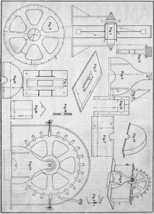
The top half of water jacket in which the nozzle is located is made by cutting two pieces of thin zinc shown in Fig. 11. Next take a strip of the heavy metal 2 in. wide and long enough to go round the half circle and have a tinsmith bend it for you to proper shape. Solder sides to this similar as described in Fig. 8, when finished will look like Fig. 12. Cut from the heavy metal 4 pieces the size given in Fig. 13, and drill holes as marked. Two of these are soldered on flanges in Fig. 12 and under the flanges in Fig. 9. This helps to stiffen the sides and keep the holes in line with one another . Clamp two of the pieces together when drilling, thus insuring the holes being in line, when top half of water jacket is placed on lower half. Use 5/8 in. stove bolts. From the same pattern, Fig. 13, cut two pieces of thick sheet rubber and lay between flanges as shown at a, Fig. 14. Punch holes to correspond with metal pieces.
For the nozzle, Fig. 15, you can have a machinist make it or you can make it yourself. Buy a 10 cent hose connection and use the male part. Make a paper cone 1 in. long to fit on shank, plugging the end, pour in from the threaded end hot solder and when set take off paper, and have it drilled similar to Fig. 15.
The sprocket wheel can be used with a chain belt but prefer a wooden wheel, and a cross section of it is shown in Fig. 16.
This will complete the making of your motor and all that remains to do is to give it a couple of coats of a good dark machine enamel, both inside and outside. This prevents any rust taking place.
Continue to:
My Books

