A Twenty Five Foot Auxiliary Yawl. IV. Finishing Frame and Deck Beams
Description
This section is from the book "Amateur Work Magazine Vol6". Also available from Amazon: Amateur Work.
A Twenty Five Foot Auxiliary Yawl. IV. Finishing Frame and Deck Beams
Carl H. Clark
The boat is now clear on the inside and all plank fastenings have been done. The entire inside would best be treated to a good coat of linseed oil and painted, to prevent its shrinking during the remainder of the work. The inside work may now be put in, beginning with the clamp, shown in Fig. 23 and in the enlarged Fig. 20. This clamp is 2 1/4 in. x 2 1/4 in. of spruce; it fits into the angle between the frames and deck beams and supports the latter.
The frames are cut off square at the level of the top of the top streak. The clamp is now bent around on the inside of the frames 1 1/2 in. in below the edge of the top streak and held in place by clamps until it is carefully adjusted. It may then be fastened into place with 1/4 in. galvanized iron rivets passing through plank, frame, and clamp, and headed over on the inside. The clamp should be in one length for each side and extend from the inside of the stem to the stern board.
Knees are fitted at the ends as shown in Fig. 21, a corner keen at the after end and curved breasthook at the bow. For the bow knee or breasthook a piece of a natural growth knee will be required. It is shaped as shown in order to fill the open space between the clamp and the plank and give a good fastening for the latter. If it is impossible to obtain the clamps in one piece the joint should be made about amidships, and a scarf piece about two feet long, fitted on the inside, as shown in Fig. 24, and through riveted.
Fig. 19.
A bilge stringer must be fitted on the inside of the frames just below the turn of the bilge as shown at b Fig. 23. It is 5 in. wide and 3/4 in. thick and should run the full length in one piece. It may be tapered in width to 4 in. at the ends if desired. It can be bent without steaming and fastened with nails into each frame. Hard pine is very good material for these bilge stringers, as it is strong and comes in good lengths although cypress or even spruce may be used.
The deck beams may now be gotten out. They are cut from stock 1 1/2 in. thick and are 1 3/4 in. deep. They are curved in such an arc that • the "crown" or curvature is 3 1/2 in. in 8 feet; or in other words, if the beam is rested upon the floor its middle point will be 3 1/2 in. above the floor; four of these beams should be of oak and the remainder of spruce. These deck beams can best be cut out at a mill where a band saw is availible. They may then be smoothed up by hand.. For the half beams alongside the standing room and cabin straight pieces are used 1 3/4 in. deep and 1 in. wide. Fig. 20 shows the method of fitting the beams. They are placed just aft of each frame. The top surface of the clamp is about level, while the under surface of the deck beam slopes, so that a notch is cut into the clamp at the right angle to fit the slope of the beam and deep enough to bring
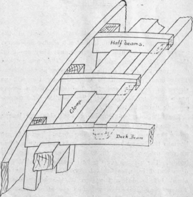
Fig. 20.
its upper surface even with the top of the top streak. The first beams to be fitted should be those at the forward and after ends of the cabin house and at the after end of the standing room. The oak beams are used for this purpose. These beams are placed at No. 2 mould, one frame aft of No. 4 mould, and at No. 7 respectively. Before cutting off the beams measurements should be taken to make sure that the widths of the hull are correct and that it has not changed shape. When the proper width is assured the beams may be cut off and fastened in place as before described. They are held into place by 1/4-in. rivets driven through beam and clamp. The remaining oak beam is now put in on the next frame forward of No. 2 mould, these two forward beams forming the mast partners. These four beams are the main stiffeners of the deck frame and must be well secured in place. The beams forward of the cabin and aft of the standing room may then be fitted, using the spruce beams. Each beam, as already mentioned, is placed just aft of each frame, being neatly let down into the clamp and fastened with a rivet. If desired as an additional fastening a galvanized nail

Fig. 23.
may be driven diagonally through the end of the beam into the frame, but this is not wholly necessary.
The half beams are next gotten out; they are 1 in. thick, 1 3/4 in. deep and 8 in. long. They are notched down into the clamp in the same manner as the others. Their inner ends will be supported by the sill, as shown in Figs. 20 and 21. The ends of the beams are notched up 3/4 in. and 1 3/4 back, to fit a corresponding notch in the sill.
The sill is in two lengths on each side, one length extending the length of the cabin trunk and the other the length of the standing room. The sills are let into the heavy beams at the ends and have notches at the proper places to take the ends of the half beams. The notches for the half beams are cut 3/4 in. deep and I in. wide; this brings the top of the sill about 1/4 in. below the tops of the heavy beams. The notches in the heavy beams are so cut that the inner edge of the sill is 9 in. from the outside of the plank and parallel to it. Sill and half beams are now fastened in place, taking care that all beams are fair and that the sill is parallel to the outside of the plank. The sills are fastened to the half beams and to the heavy beams by galvanized nails driven diagonally. The rounding corner pieces, as shown in Fig. 21, are 1 1/4 in. thick, and are fitted into the corner between the sill and the beam as a support for the curve.
The top of the stem is now cut down, leaving only the tenon as shown, about 1 in wide. The upper edge of the stem board is also trimmed off to the same line as the deck beams, so that the deck plank will be evenly across. The edge of the top streak is bevelled slightly to conform to that of the deck.
At the masts and bitt-post oak blocks are fitted between the beams and fastened through. They are 1 1/2 in. thick and about 1 1/2 feet long, with the grain running as shown. They must fit neatly under the deck and it will be necessary to plane them off somewhat rounding on the upper face to accomplish this.
The boat is now ready for the deck, which should be of fairly clear pine, 3/4 in. thick; the middle plank of the deck may, if desired, be of oak about 10 in. wide. In this case the middle plank should be laid first, taking great care that it is exactly in the middle; a line stretched from stem to stern will help in this. The other planks should then be put on about 6 in. wide, straight fore and aft. The edges of the plank should be tongued and grooved, as this makes a very tight and neat deck, which does not re
Fig. 24.
quire calking. At the edge of the deck a very wide board should be used, as in Fig. 21, at least 15 in. wide being desirable, as the curve of both cabin and gunwale are cut from it. The deck planks are nailed to each beam and to the edge of the top streak, 2-in. nails being used and the heads being "set" slightly below the surface. All joints and the under side of the deck planks should be painted before putting together. The edges of the deck plank may now be trimmed down even with the side plank on the outside, and on the inside just even with the sill and curved corner pieces.
The cabin trunk is next to be worked in; it may be of either pine or oak. It will be in two pieces joined at the forward end, each piece being about 9 ft. lang, 14 in. wide and 3/4 in. thick. A template should be made from 1/4-in. stock, by bending it around in place and laying out the outline on it. The trunk is 11 in. high at the after end, 7 1/2 in. high at the point where the curve begins at the forward end, and about 6 in. high in the middle. Having these points, the curve of the top edge can be drawn, and also the curve of the lower edge. The template is now taken down and the outline cut out. The two boards are then cut out to fit the template. The bending and fitting of these trunk sides is perhaps the most difficult part of the entire construction, on account of the width of the boards and the sharp bends, with the consequent tendency to split. They must be bent one at a time and thorougly steamed on the end which is to be bent. A rough form should be made of about the same curvature as the end of the house. When the board is sufficiently limber it is bent around the form and fastened in place to cool. More curve should be given to it than is necessary, as this makes it easier to force it into place. When it has cooled and "set" it may be set into the boat and drawn up into place by clamps. This operation is apt to split it if great care is not used; it may, however, be prevented by placing a block under each clamp to distribute the pressure. The trunk is fastened in place by screws driven through it into sills, corner pieces and beam, drawing it up tightly into place. The sides of the trunk should not be exactly vertical, but should slope inward slightly. The forward ends of the two parts of the trunk should be allowed to overlap, while fitting and fastening them in place. Both may then be cut off together to exactly fit end to end. A block of the same width and thickness is fastened on the inside to cover the joint. A brace should be fastened across the top at the end of the trunk to prevent the sides springing out.


The coaming around the standing room is of oak. 5/8 in. thick, standing 6 in. above the deck at the side. The method of fitting it is the same as for the trunk, but much easier, as it is narrower. Where it joins the trunk side it is trimmed down to 1/4 in. and let into the latter to make a smooth joint. A butt joint is made between the two portions, at the after end, in the same manner as the trunk sides.
The trunk should be painted inside and out, but the standing room coaming should be left bright and finally shellaced.
Continue to:
My Books

