A Twenty Five Foot Auxiliary Yawl. V. Cabin Trunk and Rudder
Description
This section is from the book "Amateur Work Magazine Vol6". Also available from Amazon: Amateur Work.
A Twenty Five Foot Auxiliary Yawl. V. Cabin Trunk and Rudder
CARL H. CLARK
Before completing the cabin trunk construction it will be well to build the center-board trunk as it is much more convenient to work inside the boat before the cabin beams are put in. In Fig. 13 the outline of the centerboard logs is shown. These logs are the lower plank of the centerboard trunk and fit onto the bottom, being shaped to the proper curve. They are to be cut to the shape shown, cut of 2 in. oak plank. The upper edge is jointed straight and the lower edge is curved by trial to fit the curve of the bottom. The square notches are cut to allowit to fit over the bottom braces at the ends of the centerboard slot. The location of these centerboard logs is shown in Figs. 11 and 22. The construction of the centerboard trunk is shown in Fig. 19. A "head ledge" is fitted in between the center!-board logs and extends high enough to take the ends of the side planks. 8he head edges are of oak 2 in. x 3 1/2 in. and about 2 1/2 ft. long. The one for the forward' end is straight, while that for the after end is curved to a radius of about 4 ft.
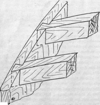
Fig. 23.
These head ledges are now et up at the ends of the slot, extending down flush with the under surface of the bottom. The centerboard logs are clamped along side of the ledges and carefully fitted. All surfaces are painted. A thread of cotton saturated with lead is laid along under each centerboard log, and also up on the side of each head ledge. The logs are now clamped tightly to the head ledges and may then be fastened down in place on the bottom. Heavy nails or screws are driven through the tapered ends of the logs into the bottom. Alongside the slot, howerer, 3/8 in. galvanized rivets should be used, headed over on both ends and spaced about 6 in. apart. A centerbore should be made for the heads of these rivets so that they will not protrude. The remainder of the side planking of the trunk may be of 7/8 in. pine, well jointed and fastened to the head ledgeswith galvanized nails, not forgetting the thread of cotton already mentioned. The top edge of the upper plank should be 2 ft. 3 in. above the bottom and should be finished level, or parallel with the water line.
Heavy nails are also driven through the logs into the ledges. Cotton calking must be driven around the sides and ends of the head ledges, working from the under side. The ends of the side plank are finished off even with the face of the ledges, and all nail heads should be 'set' down even with the surface. The top of the box is covered by a board, with rounded edges, and a slot to allow the rounded end of the centerboard to project through.
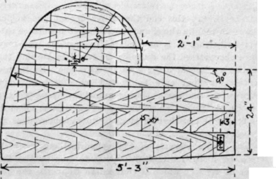
Fig. 24.
The house beams are now to be put into place. These are of oak, cut from a 3/4 in. plank, and are 1 1/2 in. deep with a crown of 6 in. in 6 1/2 feet. These beams should be neatly finished all over, and the under edges either bevelled or beaded. They are spaced 9 in. from center to center, beginning at the after end of the cabin, directly above the heavy deck beam already in place. The best way of fastening these cabin beams to the trunk is by a dovetail joint as shown in Fig. 23, not allowing them to go entirely through the trunk side, but leaving about 3/1G in. of stock at the end of the dovetail. In this way the ends do not show on the outside. In addition to the dovetail a long nail should be driven down through the end of the beam into the trunk. The upper edge of the trunk side must now be bevelled to the slope of the beams to- allow the top planking to fit smoothly.
The top plank is of pine 1/2 in. thick, tongued and grooved. It is fastened in place with 1 1/4 in. galvanized nails. It is laid and trimmed off around the edges, and the opening for the sliding hatch cut out. This opening is 30 in. wide and extends to the fourth beam, as shown in Fig. 21, making it about 27 in. long. The beams, also, are cut off. The top is now to be covered with 8 oz. duck, laid in paint, stretched tightly and tacked around the edges. If possible, this should be obtained in one piece, but if not, it should be pieced down the middle. A piece of 3/4 oak half round moulding is now bent around the upper edge of the house to cover up the tacks, and the canvas is cut off even with its lower edge.
The bulkhead of the after end of the cabin is next to be built. It is of 5/8 in. tongued and groved pine; it is fastened on the after side of the heavy deck beam and the after cabin beam, and is carried down and fastened to short pieces bent in on the plank. This bulkhead should be well fitted and fastened both to the beams above and to the plank below, as it will form a very efficient brace to prevent the boat from twisting. An opening is, of course, left of the same width as that in the cabin top. A piece of 3/4 in. oak half round at the top will cover the joint. If the heavy deck beam has not already been cut off it may now be done, leaving it just even with the opening.
The lights in the cabin trunk are each 12 in. long, forward one being 3 1/2 in. wide and the after one 4 in. The glass is rabbeted in from the outside and set in putty, and the inside corners of the opening are bevelled off.
The skeg, or deadwood, is 3 in. thick, preferably of oak. At the after end it is 16 in. deep, and it is 7 ft. long. Its lower edge is straight, while its upper edge is curved to fit the bottom. The skeg is fastened with long spikes driven from the inside, except at the extreme point, where a heavy screw is used. In driving these spikes care must be taken to keep clear of the shaft hole, the center of which is 12 in. up on the after face of the skeg. The hole for the shaft should next " be bored; the exact slope will depend upon the diameter of the fly wheel of the engine, but if a point is taken 10 in. above the bottom at mould No. 5, a line from this point to the point already mentioned on the back of the skeg will give a good line. The hole should be first bored by trial, using about 1/2 in. bit; it may then be tested by sighting, or by a line stretched between the two points. It may then be increased in size, using a large bit and taking out more on one side or the other to give it the proper direction. Its final size should be about 1 1/2 in. It is advised that this hole be lined with a piece of thin lead pipe to make the joints perfectly tight. Pipe about 3/32 in. thick should be used and it should be turned on both ends, bedded in lead and tacked with copper tacks. The inside shaft log, resting on the inside of the bottom need not be fitted unless an inside stuffing box is used, which is not common. In case it is fitted, it should be bored with the same size hole as the deadwood, and the lead pipe carried all the way through.
A piece of oak plank 2 1/2 in. thick 6 in. wide and 20 in. long is now securely fastened up and down the middle of the stern board, just above the stern knee. It forms the step for the mizzen mast and also holds rudder post tube.
The rudder post tube is a piece of 1 1/4 in. galvanized
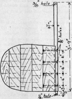
Fig. 25.
iron pipe, 18 in. long, threaded up 6 in. on one end, the other end being square. The hole for this tube is bored from the outside, just at the water line. Here again it may be necessary to bore a smaller hole and trim it out with a gouge or otherwise. The tube should be carefully fitted and greased and turned down into place with a pipe wrench. It would best not be put into place permanently until the step for the mizzen mast has been cut.
The step for the mizzen mast is a mortise about 5 in. long 1 1/2 in. wide and 2 in. deep, with its center about 6 in. aft of the center of the rudder hole. The mast hole in the deck should be directly above it and be about 3 in. diameter to be trimmed out exactly to fit the mast later.
The forward mast hole is 4 1/4 in diameter cut in the place already provided for it. The step formed of a piece of 2 1/2 in. oak plank as shown in Fig. 22 resting upon and fastened to the cross timbers of the bottom. The mortise is 4 in wide and is located with the help of a plumb line dropped from the center of the mast hole above.
The bitt post is 3 in. square and extending down mortising into the stem as in Fig. 22. It should extend 6 in. above the deck and be provided with a piece of 5/8 in. brass rod 9 in. long passing through it crosswise to wind the lines about .
The cabin floor is 6 in. above-the bottom amidships and is supported upon blocks resting upon the bottom stiffeners. The floor itself is of 3/4 in. pine or spruce.
The standing room floor is about 12 in. above the bottom at its forward end and is level. It is supported upon spruce beams about 2 in. deep and 7/8 in. wide, spaced at each frame and supported by cleats nailed to frames or plank. The floor boards are 3/4 in. thick of pine. The outer boards must be neatly fitted around the frames and some form of finishing strip worked in.
The after bulkhead at the end of the standing room is of 1/2 in. matched pine. A door should be left in it for access to the space and also a slot for the tiller to pass through.
In Fig. 24 is shown the centerboard. It is of 1 1/4 in oak or hard pine fastened together with 1/2 in. iron rods. The boring of these holes for the rods is not as difficult as would appear. The pieces should be about 6 in. wide, and should be clamped together one after another, bored, and the rods driven. If plenty of lead
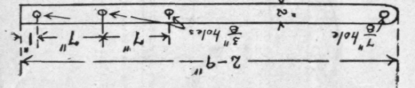
Fig. 26 is smeared on the rods they will drive very easily. The lower and after sides should be shod with pieces of 1 in. half round iron, both to protect the board and to add to its weight so that it will sink into place. For a pivot, a rowlock socket should be fitted to take the wear. It must be put into the boat from below, the boat being heeled for that purpose. A 1/2 in. bolt is thus passed through holes in the centerboard logs to support it. If rubber washers are placed under the head and nut of this bolt no leakage can take place.
The rudder is shown in Fig. 25. It is 1 1/4 in. thick at the stock and tapers to 7/8 in. at the after edge. The first board should be of oak and be fastened to the stock by 3/8 in. rivets, headed on both ends. It should be rounded out to fit neatly around the stock. The remainder of the rudder may be of hard pine put together with 5/16 in. rod in the same manner as the center-board. The stock is of 1 1/4 in. round rod, shouldered down to 3/4 in. at the lower end. The rudder is 2 ft. 3 in. long and 24 in. wide at the widest point.
The iron skeg is shown in Fig. 26; it is of 2 in x 1/2 in. flat bar, with holes drillled as shown. The iron work may be done at any blacksmith shop, the pipe may be gotten from a gas fitter and the whole sent away to be galvanized.
With the addition of a 1 1/2 in. oak half round moulding around the edge of the deck plank, the carpenter work on the boat is about complete, the only work remaing being the building of the engine bed and the fitting of seats, transoms and doors, which will be taken up next.
Continue to:
My Books

