Attachments For Speed Lathe
Description
This section is from the book "Amateur Work Magazine Vol6". Also available from Amazon: Amateur Work.
Attachments For Speed Lathe
C. Tobyansen
The ambitious carpenter who has a small private workshop should by all means include a turning lathe among his possessions. It will pay for itself, if only in the time saved by an emery wheel attachment for grinding tools. The initial cost need only be a head and tail stock. The rest, such as lathe bed or ways and flywheel, tool rest, etc., can be largely made by the carpenter himself.
Most every user of tools, be he an amateur or practical mechanic, likes to manufacture articles useful or ornamental for his home and fireside; often, also, small fancy products suitable for presents wherewith to endow friends and relatives on festive occasions, thereby tive scale. A fret or jig saw is a much needed complement in all kinds of woodworking operations. Such an attachment is shown in Fig. 1 of the illustrations, where A A represents the lathe bed or ways and B the back table. Upon this rests the jig saw, which may be fastened by screws into the ways. The attachment is made entirely of wood, as shown. The frame proper consists of the two arms D D and the pack piece E, shown in dotted lines, and on which the two arms are rigidly fastened. This frame carries the saw blade at F F and swings on the pivot at G, which is an iron bolt, passing through from side to side. As will be understood from the sketch the frame is incased be-
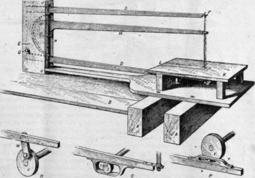
Fig 1.
saving heavy drains on his purse. And articles so made and given have a far greater valuation than a purchased present equally costly, because of the closer personal associations a home-made article brings with it, bearing more or less the stamp of the individual ingenuity, skill and taste of the maker.
Turning enters largely into the manufacture of such products, as also into the making of household furniture of all kinds. But it is not in the sense of turning only that the lathe can be made useful. By simple home-made attachments one may perform most any of the mill operations, so-called, on a small but effectween the pieces and swings freely up and down, still not so loosely as not to be properly guided. The pivot should be in the line with the top of the saw table K. The piece L is adapted to slide back and forward in order to give freer access to the lower arm for adjusting saw blade. The rod M is stationary between the sides of the case H, and is a guide for steadying the blade in the cut. It is fitted with a small, round, hardwood piece slotted to receive the blade. This hardwood piece has to be renewed from time to time as it wears, and is merely struck into a hole bored in the end of the rod for this purpose. The saw blade should be of such no length as to slightly force the arms D together, thus keeping the blade taut and stiff. The arms have at the ends a small brass plate fastened on with screws projecting about 1/2 in. beyond the wood and slotted to receive the blade. This is more plainly shown in the sketch O on the same figure, which shows the end of the lower arm. As will be seen the brass plate mentioned has a slight curvature upward. On the upper arm this curvature is downward. The saw is fastened by means of a brad passed through a hole drilled in the end of blade for this purpose. In order to drill this hole without breaking the blade it is advisable to draw the temper at its ends. If the blade is a very fine one a thin wire may be wound about the ends serving the same purpose, or the end may be slightly upset by placing the blade in a vise and hammer lightly ter devices are equally adapted to a foot-power lathe. The saw table should be high enough to allow the lathe head to pass entirely under it, bringing the face plate close up to the saw bar.
In Fig. 2 is shown a circular saw attachment, the need of which is too important to the woodworker to need comment. The saw blade is mounted on a steel arbor, which can be purchased of any machine dealer. The saw blade in the sketch need not exceed 8 in. in diameter and should be of light gauge. The arbor B is hung between two pointed centers and a dog connects it with the slotted face plate, thus complying with the motion of the lathe. The bed table D is fastened to the lathe bed by the bolt F, which reaches down to the plate F underneath the bed. A wedge driven between this and the lathe bed will fasten the

Fig. 2.
on the extreme end, thus raising a burr thick enough to prevent the saw slipping through the brass jaws. The slide L in the saw blade may also be fitted with a, sloted brass plate to receive the back of the saw blade, thereby giving a steadier vertical motion. This is rather necessary if the saw frame has worn slack in the case.
At N, O and P are shown three different devices for transforming the rotary motion, of the lathe into the reciprocal motion of the saw. The small eccentric S in the sketch O is operated by the shoulder T reaching between the centers of the lathe. This form is more especially adapted to a lathe run by steam power. This journal should be made as long as needed to give sufficient swinging room for the work, and may be further steadied by passing through blocks or rest on each side of the saw tablt, close fitting enough to prevent vibration, but still not tight enough to cause friction. Lampblack will be found an excellent lubricant to prevent the latter.
The devices shown at N and P are both adapted to operate directly from the face plate of the lathe, U and V representing face plates. In sketch N the connection with the saw bar is made by the driving rod W, which is bolted loosely to both. At P the peg X is fastened firmly to the face plate and extends through the slide Y, fastened to the saw bar. These two latsaw stand firmly. This same device may be used equally well for the jig saw. The brackets H H are fastened firmly to the bed table. The slotted piece J, which connects the bed, table and the saw table proper, is guided by the peg K and fastened by a wing nut. The table can thus be raised or lowered at will, admitting of any desirable depth of saw cut. It is further adjustable by the wing nut M, which adapts the table for bevel cutting. The piece N, inserted loosely in the saw table, is beveled in the slot on the underside to admit clearance for the saw in bevel cuts.
By placing a beveled collar on each side of the saw blade, as shown at the right in Fig. 2, the saw may be placed out of line and can be adjusted according to the bevel given the collars, which are made of wood. This is a useful arrangement, for many purposes where a wide cut is desirable, such as plowing, rabbeting, notching out for dentals, and the like. When such a saw is used the piece N must be replaced by one having a wider slot. The guide R must also be removed and replaced with a cross cuting guide adapted to cross the table and slide against the saw, the construction of which may be safely left to the reader's ingenuity. By the way, the bevel saw arrangement mentioned above is commonly called "a wabble saw."
An emery wheel can also be fastened on a saw mandrel. But it would be advisable to procure a sec1ll ond mandrel, so as to prevent too much changing about. A cheaper way is simply to turn a hardwood spindle to fit the hole in an emery wheel, so it will drive fast on the spindle, and we have our grindstone complete.
In Fig. 3, is shown an easy method whereby the edges of the work in hand may be molded in simple designs. A shows a sectional view of a center chuck, which generally is included among the fixtures when
Continue to:
My Books

