Construction And Management Of Gasoline Engines. VIII. Lubrication and Lubricating Devices
Description
This section is from the book "Amateur Work Magazine Vol6". Also available from Amazon: Amateur Work.
Construction And Management Of Gasoline Engines. VIII. Lubrication and Lubricating Devices
CARL H. CLARK
The question of lubrication is one of vital importance in gasoline engine operation. The thoroughness of the lubrication has a very direct effect upon the life of the engine. An engine may be badly damaged by a short run because of insufficient lubrication. The cylinders especially must be well lubricated, as a lack of lubrication under the extreme heat conditions will cause the piston to stick and finally cut the cylinder.


Fig. 53. Fig. 54.
The principle means for feeding the oil are illustrated in Figs. 53, 54 and 55. The first, or plain oil cup, is simply a brass casting B, screwed into place by the thread T; the screw cap G allows the body to be filled with oil, which gradually feeds down to the bearing through the hole in the stem. This style can be used for ordinary bearings where there is no outward pressure. Fig. 54 shows a grease cup for feeding the solified grease. It consists of a cap C, which is threaded inside over its entire surface. The end of this cap is closed by the fiat disc B which fits the interior thread and is provided with a stem and thread end T. In operation, the cover C is filled with grease, and then screwed down over the disc B, the pressure forcing the grease out through the holeO in the stem and on to the bearing. The cover C can be gradually screwed down until all of the grease is exhausted. This form is used where the pressure on the bearing is great, as on the main journals.
Fig. 55 shows a sight feed oil cup for feeding oil against pressure, as to the cylinder. It consists of a section of glass tube, G, closed at the ends by the heads C and F. The entral tube is a projection from the lower bead T, having its upper end threaded, over which the head C screws. The head C is screwed down tightly, with a ring of packing placed under the edges of the glass G to make a tight joint.
A threaded stopper f allows the body to be filled with oil, which can flow through the small opening o, down through the central opening and so down to the bearing. A section of smaller glass tube g is inserted, as shown, and the body has a circular opening o through which the flow of the oil from above may be observed. A side tube P leads from the lower chamber
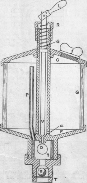
Fig. 55.
up above the body of the oil to admit the pressure and prevent the formation of a partial vacuum above, which would finally prevent the feeding entirely. The small plunger V fits into the seat just below and is held in place by the coiled spring S.
The lever L is pivoted to the end of the plunger V; when this lever is horizontal it is free and the plunger V is in its seat, stopping the flow of oil. When L is raised to a vertical position it raises the plunger V and allows the oil to feed. This lever L, in its upright position, bears on the top of the cap R; this cap is threaded on the end of the central stem, and may be raised or lowered, thus regulating the amount which the plunger V is raised by the lever L.
The ball B is designed to prevent a sudden inrush of pressure by being carried up into and closing the opening just above. The whole device is, of course, exposed to the same internal pressure, so that the oil
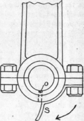
Fig. 56.
can feed by the action of gravity. The ball B prevents the pressure blowing through into the cup above and allows the plug f to be removed and the cup filled while the engine is running. By turning down the lever L the supply may be stopped when the engine is not running.
The lubrication of the cylinder is done by means of a sight feed cup so placed as to deliver oil at a point near the middle of the piston stroke. This oil cup is

Fig. 57.
shown at 0, Figs. 8, 9 and 11. The lubrication of the piston is one of the most important and is perhaps the most difficult point to lubricate.
The high temperature of the cylinder, which is estimated at at least 1500 degrees, is sufficient to burn almost any kind of oil. The carbon deposit thus formed gathers in the counterbore, and passages, and on the igniting gear or spark plug; such a mass of carbon will frequently become heated and fire the charge during the compression stroke, causing pre-ignition. The gathering of the soot on the sparking points also insulates them and partially or entirely prevents sparking. Cylinder lubrication and, in fact, all lubrication is improved by a judicious use of graphite. This substance has the quality of filling up the small pores of the iron and rendering the surface smooth and glassy. A new cylinder especially is greatly benefited by the use of graphite, as with even the most careful finishing of a cylinder there are innumerable minute cavities, each of which is a small producer of friction. Graphite will fill up these cavities and give the surfaces of piston and cylinder the glassy effect which denotes the proper condition. The smoothness of the surfaces allows a better fit of the piston rings, which increases the compression. The lessened friction also increases the life of the cylinder.
Graphite may be fed into the cylinder with the oil through the regular cup. This, however, is not advisable, as it is apt to clog the small openings and an independent method is desirable. If a priming cup is fitted to the engine the graphite may be fed through it after being mixed with a small amount of kerosine or cylinder oil. It may also be fed in through the spark plug opening, but care must be taken to not allow any flakes to lodge upon the spark plug, which will cause a short circuit. It is not always advisable to depend upon the graphite alone, but by its use less oil and a thinner oil will be needed, with proportionately less trouble from carbonization.
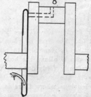

Fig. 58.
The wrist pin as a rule requires and receives scanty lubrication. An axial hole is usually provided with a radial hole opening into the bearing. Oil from the cylinder walls is supposed to work its way along this hole and into the bearing; very little, however, can da so. The rotation of the rod is slight, however, and much oil is not required.
The crank pin is lubricated in one of several ways, the most common of which is the splash system, mentioned in connection with Fig. 8, a detail of which is-shown in Fig. 56. The small scoop 8 is made of sheet metal, and held in place by the bolts as shown. The base is partially filled with oil, a small portion of which is scooped up at each revolution and delivered to the bearing above through the small hole O. The direction of revolution is shown by the arrow. By the splashing of the connecting rod, some oil is also delivered to the cylinder walls. A very reliable method of crankpin lubrication is illustrated by Fig. 57; a small hole is drilled in the center of shaft, crank and pin to the surface of the crankpin bearing. It is drilled, as shown by the dotted lines, and plugs inserted to close the openings. This hole extends through to the front of the engine where a grease cup is fitted into the end of the shaft; in this way the grease may be placed directly upon the bearing. This method is good, but is somewhat in the way when using the starting handle. Another idea, which is used on some high grade engines is shown in Fig. 58. It consists of a shallow receptacle with an open centre forming a sort of ring, which is fastened to the side of the crank. This receptacle is drawn out at one point, at which there is a hole communicating with the axial hole 0 in the crank pin. Oil is delivered into the lip by the tuber from an oil cup above. As the shaft revolves the oil is thrown into the circumference of this ring and finds its way to the bearing through the hole 0. In this way a continuous feed may be had.
The main bearings of two cycle engines are usually fitted with grease cups, as at G in Figs. 8. 10, and 11, mainly because the grease by its viscosity prevents the loss of base compression by leakage through the bearings. Where an open base is fitted, as in Figs. 16 and 17, a cup for oil may be used as at or even a cup like Fig. 53.
On engines with several cylinders it is customary to fit a multiple sight feed oiler, having several supplies, each operating like Fig. 55. Each important bearing is then fed by a separate supply.
There are several varieties of forced feed oilers consisting of several small pumps run by a common shaft and each supplying a bearing. The shaft is run by gearing or belt from some part of the engine. The use of the forced feed oiler assures a steady supply to each bearing, and this supply stops automatically on the stopping of the engine.
The smaller bearings are fitted with the screw cap oil cups or simply a countersunk hole to receive a few drops from an oil can.
It is a practice of some people to mix the lubricating oil with the gasoline in the proportion of about a pint of oil to five gallons of gasoline. The presence of the oil seems not to affect the vaporization, and the oil is thus carried to all the working parts of the engine which are in its path. It also avoids the necessity of filling and watching the oil cups.
The question of the amount of lubrication is a matter of experience with the particular engine in operation and can only be settled after a considerable amount of experiment.
Continue to:
My Books

