


How To Make A Needle Telegraph
Description
This section is from the book "How To Make Common Things. For Boys", by John A. Bower. Also available from Amazon: How to Make Common Things.
How To Make A Needle Telegraph
A needle telegraph is merely a galvanometer with the needles vertically arranged, and a key to reverse the electric current. You have already found out with your galvanometer that with a current of electricity - we use the words of your Science book here - going in one direction the needle moves from left to right; if the wires are reversed, the needle moves from right to left. Instead of moving the wires, the key reverses the current. Now for the simplest way of making such an arrangement. Take the side of a cigar-box, smooth it, and see that the sides are parallel. Cut one into the shape of a small Gothic arch, as in Fig. 146. Take a piece of wood a trifle wider than the side of the box, and 6 inches long; hollow out a groove exactly large enough for it to stand on end, as shown in Fig. 146, a. Put a square block at each corner; fix them with glue, and glue in the upright piece. While this is drying, make the coil of wire as in the galvanometer, but make it of thinner wire, winding it on a cardboard frame. Leave several inches of wire free at each end of the coil. This bobbin we show at 6, Fig. 146. Then fix the coil on the back of the dial, as we will now call the upright piece. Now prepare a magnetic needle to swing within the coil, as in the galvanometer. This time, however, you must drill a hole through the centre, which you can do when it is hot and soft, and fasten it to a wire passing through it This you can do with a little sealing-wax; put it on neatly. The wire must be long enough to pass through the dial in front and the coil behind. Bore a hole in the dial exactly opposite to one in a slip of wood that is to be fastened at the back of the coil. In these holes put a short length of fine glass tubing, so that the axis of the needle can vibrate with as little friction as possible. Fasten a stop of some kind on the wire carrying the needle, so that it does not easily slip out. To the end of the wire coming through the face of the dial, a pointer, cut in the shape of the needle, must be fixed, so that when the needle in the coil moves, the front one moves with it, and with similar movements - this is the pointer. Above the centre of the needle in front put in two stops, either of wire or wood, so that the needle can only vibrate through a limited arc, as shown in Fig. 146. Before going any further, see that the needle in the coil moves freely, and that models we must refer you to your book on Electricity. This will also give you a copy of the dial, with directions as to how many motions a needle must make to right or left for the formation of a letter. You will find two Daniell's cells enough for a pair of instruments of this kind. If you think it worth while to make a double- key-board by screws passing through B and F. A second strip of brass must be screwed flat to the board along A, Et in front and parallel to $, F. Attach some wooden or ivory knobs on the springs, immediately over the strip A, E. These are for pressing down the spring into contact with A, E. When released they fly back to B, F. Now look carefully through the whole arrangement, and see you have got your keyboard properly laid out, the brass strips and springs properly fitted. At the ends c, d of the springs, fasten two binding-screws; do the same at A, B. Now bring the wires down from the galvanometer, and attach them to the screws, C, D, and put the wires from the battery on at A, B. By pressing down one key you will find the battery current will make the needle turn in one direction; by pressing down the other, the needle will turn in the opposite direction. If you have followed out our instructions you will have an instrument that will enable you to go through the telegraphic alphabet. The signals for each letter should be marked carefully on a sheet of writing-paper or cardboard, and pasted on the dial-board at the back of the needle. With a pair of such instruments you can send messages from one room to another, or from house to house; but your friend who has to receive the message must be able to read the signs the needle makes. You must remember that when your needle turns to the right or left, the needle of the second instrument will do the same if you have joined up the wires correctly. Fig. 148 shows how the battery is to be joined to the instrument - the needle of the instrument being marked "a" Now for the scientific working of the of the small pulleys used by the Venetian blind-maker. Wind each with about half an ounce of silk-covered wire, No. 36. This number refers to size, so that if you ask for this at an electrician's, he will know what to give you. Moreover, if you tell him for what you require it, he will also supply you with bobbins and magnets as well. You must next have a wider cylinder for the mouthpiece of your telephone. It must be hollowed out, so that it will contain the bobbin. You can sometimes get wooden tooth-powder boxes that will suit for this purpose. If not, take a short length of a thick window-pole; and after hollowing it out, like the inside of a box, you can fit it, as shown in Fig. 149. Wind the wire on the bobbins; leave the two ends of each free. Then in front of the box fix a piece of very thin sheet-iron; that used by photographers for ferrotypes is best Keep it quite smooth, and cut off a portion large enough to cover the mouthpiece. Now put on the lid, after cutting out a circular portion in the top of the lid about the size of a sixpence. Then put it on so that it holds the iron plate in position. Push up the magnet to about 1/16 of an inch from the plate; fasten it there either by plugging it, or by putting a short screw in at the side so it grasps the magnet and holds it firmly. Now bore two small holes at the back of the box, through which bring the ends of the wires from the inside coil. Attach the wires to two binding-screws, the stems of which can be screwed into the box. Cut off the cylinder which holds the magnets to about ¼ inch longer than the magnets themselves. Fill up the holes with plugs of cork.

Fig. 146. - Separate parts for Needle Telegraph.
a. Dial and base; b. coil; e. needle for inside of coil; d. pointer to swing on the face of the dial.
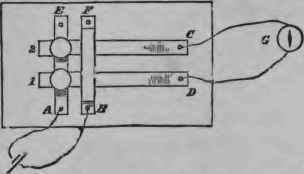
Fig. 147. - Plan of keys for reverse current.

Fig. 149. - Section of the Telephone. m. The magnet; c. the bobbins of wire; /. the thin plate held by mouthpiece; b. binding-screws attached to line wires.
Cut them off neatly, then screw or glue on the lid, keeping the centre opening in front, so that the edge of the opening nearly touches the ferrotype disc. At an electrician's you can get all the parts ready to put together for telephone-making. You may prefer this plan; it makes the method of providing the cylinders easy, and at the same time ensures perhaps a neater pair of instruments than you can make without this aid. Read up from your book the whole science of this instrument; then you will not be likely to make any mistakes in its construction.
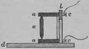
Fig. 150. - A Simple Microphone. a. Carbon blocks and pencil; b. upright support; c battery screws; d. base of instrument.
In Fig. 149 we show the various parts of this instrument. To increase the loudness of the sound a microphone is frequently introduced with the telephone. It is so easily made that we will here give directions for doing so. At the electrician's, secure two blocks of carbon, such as is used for batteries; about a cubic inch of each. Bore two holes through them, and secure at the same time two binding-screws with long stems. Have a small pencil of charcoal, such as is used for electric lighting, Cut off about 4 inches; point both ends of this by rubbing down with a file as you would in sharpening a lead pencil. In two sides of the blocks make hollows by boring with a rat-tailed file, so that the pencil-piece can rest lightly in these hollows, and be supported by the blocks. Screw the blocks to a board, at such a distance that the pencil is supported, as in Fig. 150; the telephone may be used with it by joining the battery wire from a telephone to one of the screws c, and from the screw c join a wire to the second telephone screw. Then the microphone, telephone, and battery will all be in the "same circuit".
By reading carefully descriptions of scientific instruments from your books, you may be able from the instructions we have given in this chapter to make several others, and in the statical electricity department still more.
We only need name the gold-leaf electroscope, the electrophorus, various conductors and insulators, carrier ball, pith-ball electroscope, and other arrangements which are so well described in various textbooks on electricity, that we need give no detailed description of them. Having gained some proficiency in these, you may at last be able to manage to make a Wimshurst and other forms of electrical machines.
Continue to:


My Books

