Hunt's Improved Steam Packing Piston
Description
This section is from "Scientific American Vol. XVII, No. 26", by Munn & Co. Also available from Amazon: Scientific American Science Desk Reference.
Hunt's Improved Steam Packing Piston
Engineers are aware that there are more or less objections to the use of the ordinary spring pistons, owing to the changing tension of the springs, the necessity of frequent adjustment, and the impossibility of the packing rings adapting themselves to the varying pressures of the steam on the piston. A number of attempts have been made to produce a self packing or steam expanding piston, which will act always with the pressure of the steam and the velocity of the engine. The advantages of such a piston will be readily appreciated by practical engineers, especially drivers of locomotives, working, as they nearly all do, at a very high pressure of steam. The general complaint against the several packings in use on our railroads is, that they "pack too tight," and rapidly wear out the rings, while the only remedy has been, the extremely uncertain one of contracting the openings by which steam is admitted under the ring, or rings, to expand them. The obvious objection to such an arrangement is, that it allows the steam to act on the rings with its full force during slow motion, as when a train is starting, while if effective under any circumstances, it will be so only at comparatively high piston speed. The efficacy of such a remedy, if it possesses any, is in fact inversely as the piston speed.

Fig.1
Fig. 1 is a perspective of the piston itself, or the "spider," with its follower and its rings removed, which are shown in Fig. 2. Fig. 3 is a cross section of another form of the piston, to be presently described, but which will serve to explain that shown in Figs. 1 and 2. Next to the core of the spider are two narrow internal rings, A, in Figs. 1 and 3; surrounding these two outer rings, B, the cross section of which is of L-form, as seen in Fig. 3. The lips of these outer rings extend to the whole thickness of the piston. The flange head of the piston, and also the follower, are turned beveling on their edges to admit the steam around the annular space thus formed under the rings, B. These spaces are plainly exhibited at C, in Figs. 2 and 3. Both inner and outer rings are adjusted to the bore of the cylinder by means of the gibs, D, and set screws seen in Fig. 1.
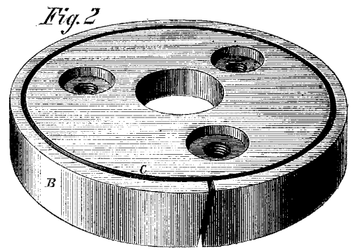
Fig.2
The section, Fig. 3, represents a modification intended for use in vertical cylinders, if considered necessary. The additional center ring, E, is intended to prevent leakage through the cut in the expanded ring and over the face of the unexpanded one, which might occur when the rings and cylinder should become so worn that the rings, when not expanded, should collapse and leave the surface of the cylinder. The rivets, F, shown by the dotted lines, are placed near the cuts in the L-rings, and are intended to hold the outside and inside rings together at that point, and prevent any tendency on the part of the latter to collapse and let steam under that part of the L-rings. Probably, however, if the packing is properly constructed and adjusted in the first instance, these devices will be unnecessary. In horizontal cylinders the weight of the piston, if properly supported on the set screws and gibs, will accomplish these objects, if the cuts in the L-rings are placed near the bottom side of the cylinder. The steam enters the annular space between the beveled edges of the spider flange and follower and the inner periphery of the overhanging part of the L-rings, and acts only on that part.
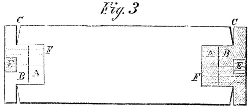
Fig.3
Patented by Nathan Hunt, Sept. 17, 1867. For further information address the patentee, or Sharps, Davis & Bonsall, Salem, Ohio, who will furnish piston heads to order on receipt of size of cylinder and piston rod.
Continue to:
My Books

