Electric Launches. Part 5
Description
This section is from "Scientific American Supplement". Also available from Amazon: Scientific American Reference Book.
Electric Launches. Part 5
The insulation resistances must be as high as possible; the insulation can never be too good. The motor should he made to run at that speed at which it gives the greatest power with a high efficiency, without heating to a degree which would damage the insulating material.
Before fixing a motor in its final position, it should also be tested for power with a dynamometer, and for this purpose a Prony brake answers very well.
An ammeter inserted in the circuit will show at a glance what current is passing at any particular speed, and voltmeter readings are taken at the terminals of the machine, when the same is standing still as well as when the armature is running, because the E.M.F. indicated when the armature is at rest alone determines the commercial efficiency of the motor, whereas the E M.F. developed during motion varies with the speed until it nearly reaches the E.M.F. in the leads; at that point the theoretical efficiency will be highest.
Calculations are greatly facilitated, and the value of tests can be ascertained quickly, if the constant of the brake is ascertained; then it will be simply necessary to multiply the number of revolutions and the weight at the end of the lever by such a constant, and the product gives the horse power, because, with a given Prony brake, the only variable quantities are the weight and the speed. All the observations, electrical and mechanical, are made simultaneously. The electrical horse power put into the motor is found by the well known formula C x E / 746; this simple multiplication and division becomes very tedious and even laborious if many tests have to be made in quick succession, and to obviate this trouble, and prevent errors, I have constructed a horse power diagram, the principle of which is shown in the diagram (Fig. 1).
Graphic representations are of the greatest value in all comparative tests. Mr. Gisbert Kapp has recently published a useful curve in the Electrician, by means of which one can easily compare the power and efficiency at a glance (Fig. 2).
The speeds are plotted as abscissae, and the electrical work absorbed in watts divided by 746 as ordinates; then with a series-wound motor we obtain the curve, EE. The shape of this curve depends on the type of the motor. Variation of speed is obtained by loading the brake with different weights. We begin with an excess of weight which holds the motor fast, and then a maximum current will flow through it without producing any external work. When we remove the brake altogether, the motor will run with a maximum speed, and again produce no external work, but in this case very little current will pass; this maximum speed is om on the diagram. Between these two extremes external work will be done, and there is a speed at which this is a maximum. To find these speeds we load the brake to different weights, and plot the resulting speeds and horse powers as abscissae and ordinates producing the curve, BB. Another curve,
e = B/E
made with an arbitrary scale, gives the commercial efficiency; the speed for a maximum external horse power is o a, and the speed for the highest efficiency is represented by o b. In practice it is not necessary to test a motor to the whole limits of this diagram; it will be sufficient to commence with a speed at which the efficiency becomes appreciable, and to leave off with that speed which renders the desired power.
I have now to draw your attention to a new motor of my own invention, of the weight of 124 lb., which, at 1,550 revolutions, gives 31 amperes and 61.5 volts at terminals. The mechanical horse power is 1.37, and the coefficient 373.
 Ohms.

Armature resistance 0.4 w.

Field-magnet resistance 0.17 w.

Insulation resistance 1,500,000 w.
This motor was only completed on the morning before reading the paper; it could not, therefore, be tested as to its various capacities.
We have next to consider the principle of applying the motive power to the propulsion of a launch. The propellers hitherto practically applied in steam navigation are the paddle-wheel and the screw. The experience of modern steam navigation points to the exclusive use and advantage of the screw propeller where great speed of shaft is obtainable, and the electric engine is pre-eminently a high-speed engine, consequently the screw appears to be most suitable to the requirements of electric boats. By simply fixing the propeller to the prolonged motor shaft, we complete the whole system, which, when correctly made, will do its duty in perfect order, with an efficiency approaching theory to a high degree.
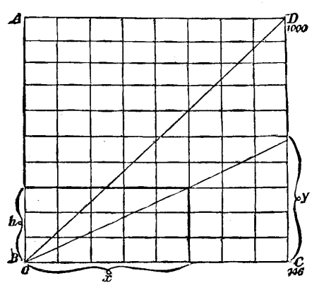
FIG. 1.--RECKENZAUN'S ELECTRICAL HORSE POWER DIAGRAM.
Draw a square, A B C D--divide B C into 746 parts, and
C D into 1,000 parts, or, generally, let a division on C D
be 0.746 of a division on B C, so that we can use the
horizontal lines cutting A B as a horse power scale.
A B, in the above diagram, gives 1,000 horse power, if
the line B C represents 746 volts, and C D 1,000 amperes.
Let x = any number of volts, y the amperes,
and h the horse power, then
h/x = y/100 :. h = xy/746
A fine wire or thread stretched from o as a center to the
required division on C D will facilitate references.
Whatever force may be imparted to the water by a propeller, such force can be resolved into two elements, one of which is parallel, and the other in a plane at right angles to the keel. The parallel force alone has the propelling effect; the screw, therefore, should always be so constructed that its surfaces shall be chiefly employed in driving the water in a direction parallel to the keel from stem to stern.

Fig. 2--KAPP'S DIAGRAM.
Continue to:
My Books

