Munro's Telephonic Experiments
Description
This section is from "Scientific American Supplement". Also available from Amazon: Scientific American Reference Book.
Munro's Telephonic Experiments
Mr. J. Munro, whose name is well known not only as a very clear writer upon electrical subjects, but as an original investigator, has recently, with the assistance of Mr. Benjamin Warwick, been conducting a most interesting experimental investigation of the action of the microphone as a telephonic transmitter, with the result of proving that metals may advantageously be employed in the place of carbon in a transmitting instrument, a practical development of one of the very earliest of Professor Hughes' microphones. The fact that metallic electrodes can practically be employed in microphonic transmitters has been denied of late with so much assurance and in such high quarters, that Mr. Munro's successful applications of that portion of Professor Hughes' discovery possess an especial interest, and must to a considerable extent affect the aspect of litigation in future contests in which the discovery of the microphone and the invention of the carbon transmitter are vital points at issue.
In investigating the properties of metallic conductors employed in the construction of microphones, Mr. Munro's first experiments were made with wires. These, in some cases, were caused by the action of a diaphragm, to rub the one on the other in such a manner as to make the point of contact vary (under the influence of the vibrations of the diaphragms) on one side or other of a position of normal potential, so that by the movement of a wire attached to a vibrating tympan along a fixed wire conveying a current from a battery, and thereby shunting the current at various positions along the length of the fixed wire, the strength of the current in the derived circuit, in which was included a suitable receiver, was varied accordingly. In other experiments mercury was employed, either as a sliding-drop, inclosing the fixed wire, or as an oscillating column; but these experiments, though instructive and interesting, did not for various reasons give encouraging results with a view to the practical application of the principle.
They, however, led Mr. Munro to proceed with compound wire structures, such as gratings resting upon or rubbing against one another, and one of the first experiments in this direction proved very successful, and led Mr. Munro to the construction of his gauze telephone, which is the most characteristic and efficient of his practical apparatus.
This instrument consists essentially of two pieces of iron-wire gauze, the one fixed in a vertical plane, and the other resting more or less lightly against it, the pressure between them being regulated by an adjustable spring or weight. These gauze plates are so connected in a telephonic circuit as to constitute the electrodes of a microphone; for touching one another lightly in several points, they allow the current to be transmitted between them in inverse proportion to the resistance offered to it in its passage from one to the other. Under the influence of sonorous vibrations the one plate dances more or less on the other, thus varying the resistance; and very perfect articulation is produced in a telephonic receiver included in the circuit. The gauze transmitter so constructed may be fixed within a wall-box with or without a mouthpiece; but as the sound waves acting directly upon the gauze plates set them into agitation through their sympathetic vibration or by direct impact, no sort of diaphragm or equivalent device is necessary, and none is employed.
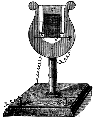
FIG. 1.
A convenient form of this apparatus is shown in Fig. 1, and to which the name of "The Lyre Telephone" has been given from its resemblance to that impossible musical instrument. In this apparatus, G¹ is a plate of iron wire gauze stretched vertically between two horizontal wires attached to a lyre-shaped framework of mahogany; against the plate rests the smaller plate, G², the normal pressure between them being regulated by an adjustable spring acting in opposition to a weighted lever, W. The two plates are connected respectively with the attachment screws, X and Y, by which the instrument is placed in a circuit with a battery and telephonic circuit.
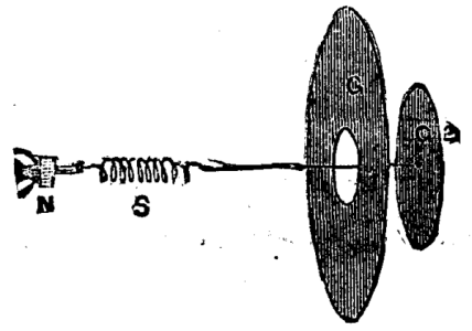
FIG. 2.
A modification of this apparatus is shown in the diagram sketch, Fig. 2, which will probably be a more practical form. In this instrument the electrodes consist of two circular disks of iron wire gauze of different diameters, the larger disk, G¹, which is fixed, being pierced with holes of smaller diameter than the smaller disk, G². In the diagram the two disks are shown separated for the purpose of explanation, but in reality they rest the one against the other; the smaller and movable disk, G², is held up against G¹ with greater or less pressure by the spiral spring, S, the tension of which can be adjusted by a screw or other suitable device at N. This form of the apparatus is more suitable for inclosure in a wall box with or without a mouthpiece, but it does not require the employment of any kind of diaphragm or tympan. Mr. Munro can employ with all his instruments an induction coil for installations where the resistance of the line wire makes it desirable to do so; the microphone and battery being included in the primary circuit and the telephones in the secondary.
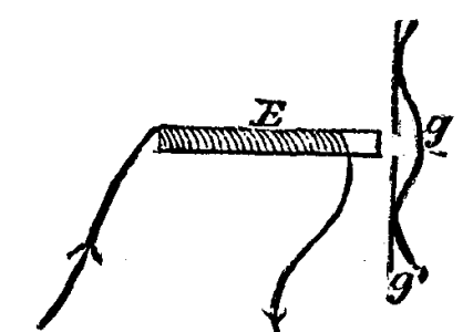
FIG. 3.
Fig. 3 is an ingenious arrangement devised by Mr. Munro, in which the adjusting spring or weight is substituted by a magnet which may be either a permanent or an electro-magnet. The figure shows an arrangement in which the fixed gauze, g¹, is perforated as in the apparatus illustrated in Fig. 2, and the movable electrode, g, is bent or dished so as to press upon g¹ around its edge. E is a magnet which by its attractive influence upon g holds t up against g¹ with a pressure dependent upon its magnetic intensity and upon its distance from the gauze. By making E an electro-magnet, and including its coil in the telephonic circuit, an instrument may be constructed in which the normal pressure between the electrodes can be automatically adjusted to the strength of the current, and in cases where an induction coil is employed the magnet, E, may be the core of such a coil.
Continue to:
My Books

