Some Recent High-Speed Twin Screws. Part 3
Description
This section is from "Scientific American Supplement". Also available from Amazon: Scientific American Reference Book.
Some Recent High-Speed Twin Screws. Part 3
 HIGH SPEED TWIN SCREWS.

---------------------------------------------------------------------

|Ship A.|Ship B.|Ship C.|Ship D.|Ship E.|Ship F.

---------------------------------------------------------------------

Length, ft. | 325 | 315 | 300 | 300 | 220 | 250

Breadth, ft. | 68 | 61 | 56 | 46 | 34 | 32½

| | | | | |

Draught on trial, | 26 ft | 24 ft | | 15 ft | 12 ft | 13 ft

forward. | 2 in | 6 in | .... | 6 in | 10 in | 1 in

| | | | | |

Draught on trial, | 27 ft | 25 ft | | 19 ft | 15 ft | 14 ft

aft. | 3 in | 6 in | .... | 9 in | 2 in | 7 in

Displacement, | | | | | |

tons. | 9,690 | 7,645 | 5,000 | 3,584 | 1,560 | 1,544

I.M.S., sq. ft. | 1,560 | 1,287 | 1,000 | 744 | 438 | 392

Speed of ship, | | | | | |

knots. | 16.92 | 17.21 | 18.75 | 18.18 | 16.91 | 17

I.H.P. |11,610 |10,180 | 8,500 | 6,160 | 3,115 | 3,045

Revolutions per | | | | | |

minute. | 107.2 | 88 | 120 | 122.6 | 150.4 | 132.1

| | | | | |

Pitch of | 19 ft | 22 ft | 18 ft | 17 ft | 12 ft | 14 ft

screw. | 5 in | | 9 in | 6 in | 7½in | 9 in

| | | | | |

Slip. per cent | 17.6 | 10 | ... | 14.2 | 9.7 | 11.4

| | | | | |

Diameter of | 15 ft | 18 ft | 14 ft | 13 ft | 10 ft | 11 ft

screw. | 6 in | | 6 in | | 6 in |

| | | | | |

Diameter of | 4 ft | 4 ft | 3 ft | 3 ft | 2 ft | 2 ft

boss. | 4 in | 11 in | 9 in | 5 in | 9 in | 10 in

Number of blades | 4 | 4 | 3 | 3 | 3 | 3

Blade area of one | | | | | |

screw. | 72 | 87 | 60 | 47 | 24 | 24

Shape of blade. |Fig. 2.|Fig. 3.|Fig. 2.|Fig. 2.|Fig. 4.|Fig. 4

Pitch | | | | | |

---------- | 1.25 | 1.22 | 1.3 | 1.34 | 1.2 | 1.34

Diameter | | | | | |

Disk | | | | | |

-------- | 2.62 | 2.92 | 2.75 | 2.82 | 3.6 | 3.96

Blade area | | | | | |

Immersion of | 9 ft | 5 ft | | 4 ft | 2 ft | 1 ft

screw. | | 3 in | .... | 4 in | 9 in | 10 in

--------------------------------------------------------------------
The slips of these screws vary from 10 to 17½ per cent., which is certainly not an extensive range, considering the widely different working conditions. Slip, as an indication of the efficiency of the screw, is not only an interesting subject, but it is often one of importance. In these ships, however, there is nothing about the slips which would give rise to any doubts as to the fitness of the screws for their work.
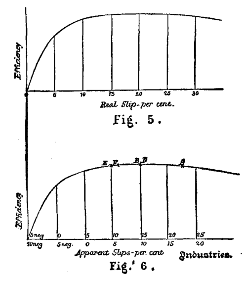
FIG. 5. & FIG. 6.
The ancient fallacy that small slip meant a high screw efficiency was supported by the great authority of the late Professor Rankine. Experience proved that considerable slips and efficient screws were companions. The late Mr. Froude offered an explanation of this general rule in a paper read before this Institution in 1878, and gave a curve of efficiency with varying true slip. In Mr. R E. Froude's paper last year there was a form of this curve, with an arbitrary abscissa scale for the slip, devised to illustrate in one diagram the wide conditions covered by his experiments. In the screws now under consideration, the values of the pitch/diameter vary only from 1.2 to 1.34, and for these the abscissa values for the same slips do not differ much. Taking the mean value, and bringing the slips to a common scale, Fig. 5 is obtained, which would approximately represent the relation between the efficiency of any one of these screws and its true slip, if this curve were applicable to full sized screws propelling actual ships. The slips in Fig. 5 being real or true, are not the slips of commerce, which are the apparent slips, such as those given in the table. Let us endeavor to split up these real slips into the apparent slips and another item, the speed of the wake.
We then at once meet with the difficulty that the wake in which the screw works has not a uniform motion. Complex, however, as are the motions of the wake, the screw may be assumed to work in a cylinder of water having such a uniform forward velocity as will produce the same effect as the actual wake on the thrust of the screw. It is then readily seen that the real slip is the sum of the apparent slip and the speed of the hypothetical wake. To make this clear, let V be the speed of the ship, Vs the speed of the screw, i.e., revolutions × pitch, and V the speed of the wake; then -
 Apparent slip = Vs - V.

Real slip = Vs - speed of ship with respect to the wake.

" = Vs - (V - V) = (Vs - V) + Vw.

" = Apparent slip + speed of the wake.
If the apparent slip be zero, the real slip is the speed of the wake, and if the apparent slip be negative, the real slip is less than the speed of the wake. The real slip is greater than the apparent slip, and can never be a negative quantity. From Mr. Froude's model experiments, it appears that this speed of wake for the A class of ship amounts to about 10 per cent. of the speed of the A screw. If this value is correct, then the real slip is (10 + 17.6) per cent., or 27.6 per cent. This is shown in Fig. 6, where O is the point of no slip, being 17.64 from the point of real slip. Slips to the right of O are positive apparent slips, slips to the left are negative apparent slips. The vessel F would certainly have a wake with a speed considerably less than that of A's wake. From the model experiments, the wake for F is about one-half that for the A class, or, roughly, 5 per cent. of the speed of the screw. For the ship F, O is the point of no apparent slip, and the real slip is (5 + 11.4) or 16.4 per cent. For E, the point of real slip is approximately the same as for F. For B and D, the positions on the curve would be about the same. The ship B has a higher speed of wake than D, but the screw D has the greater apparent slip.
The influence of the number of blades on the scale for the slip has been neglected. If this efficiency curve were applicable to full sized screws propelling actual ships, and if the determination of the wakes were beyond question, then we should have a proof that our screws were at or near the maximum efficiency. But, as we know, from the total propulsive efficiencies, that the screws have high and not widely different efficiencies on these ships, we may argue the other way, and say that there is good reason to consider that at least the upper part of the curve agrees with experience obtained from actual ships. Now take Fig. 6 and consider the general laws there represented. Take the speed of the wake as 10 per cent. of the speed of the screw, which is probably an average of widely different conditions, including many single as well as twin screw ships. Then this curve shows that considerable negative slips mean inefficient screws; that screws may have very different positive slips without any appreciable difference in their efficiencies; and that very large positive slips and inefficient screws may be companions.
Continue to:
My Books

