Apparatus For The Manufacture Of Acetylene Gas. Continued
Description
This section is from "Scientific American Supplement". Also available from Amazon: Scientific American Reference Book.
Apparatus For The Manufacture Of Acetylene Gas. Continued
A cock, H, placed at the lower part of the apparatus, permits of clearing the piping in case a condensation of water occurs.
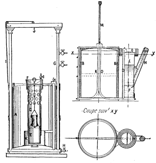
Figs. 5, 6, and 7. - LEQUEUX-WIESNEGG ACETYLENE APPARATUS
The apparatus represented in Figs. 6 and 7 is continuous. It consists of an apparatus with two holders, that is to say, so arranged as to put the least liquid possible in contact with the gas produced, and to thus prevent absorptions and losses. This gasometer consists of a tank, A, of a movable holder, C, and of a stationary holder, B. The generator, E, is formed of a cylinder, at the bottom of which there is a bucket, F, designed for the reception of the greater part of the lime resulting from the reaction. It is closed by a cover, G, arranged with a simple or multiple joint, according to the precision that it is desired to obtain and that may reach 30 centimeters of water. The figure represents the holder at the bottom of its travel.
Mr. Edward N. Dickerson's Apparatus (Figs. 8 to 13). - Mr. Dickerson, of New York in June, 1895, patented several arrangements permitting of automatically regulating the production of acetylene in measure as it is consumed. In the apparatus represented in Fig. 8 the water is led from a sufficiently high reservoir, A, through the pipe, B, into the gas generator, D, and over the carbide, C, placed upon a grate, O. The acetylene forms when the water reaches the carbide, and its disengagement ceases when the pressure forces the water back. The gas passes through the intermedium of a cock, e, into the pipe, W, provided with a cock, Z, into the automatic regulator, G, and then into the gasometer, P R. Between the regulator, G, and the gasometer, Mr. Dickerson interposes an arrangement consisting of an engine, H, actuating an air pump, K, through the pressure of the gas when it is desired to introduce a mixture of acetylene and air into the gasometer. This arrangement is evidently useless when it is desired to collect the acetylene alone.
The gas upon making its exit from the gasometer flows through the pipe, T, to the burners, V.
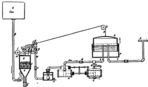
Fig. 8 - DICKERSON ACETYLENE APPARATUS, WITH AUTOMATIC REGULATION.
When the holder, R, is filled, the cord or chain, a, passing over the pulley, b, revolves the sector, c, until the pin, g, meets the counterpoised lever, d, of the stopcock, e. In the return of the chain, the other pin, o, carries the lever back to the position shown in the figure.
The gas generator, D, is provided with a discharge cock, E, and a charging aperture, m.
Figs. 9 to 13 show another of Mr. Dickerson's apparatus that permits of an intermittent automatic distribution either of the water upon the carbide or of the carbide in the water in regulating such distribution through the displacement of the holder of a gasometer that collects the excess of gas necessary for the consumption.
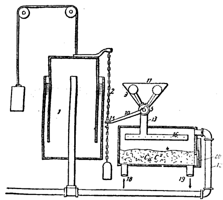
Fig. 9. - DICKERSON ACETYLENE APPARATUS, PERMITTING OF THE AUTOMATIC INTERMITTENT DISTRIBUTION OF WATER UPON CARBIDE OF CALCIUM.
Mr. Dickerson rightly remarks that it is disadvantageous to directly control the distribution of the water upon the carbide by means of the holder of the gasometer. In fact, the water cock may remain open before the holder has moved, and there may thus fall upon the carbide an excess of water, giving rise to a production of acetylene greater than the capacity of the holder warrants.
The object of the Dickerson apparatus is to prevent such overproduction and to furnish water or carbide to the gas generator only as long as the gasometer will have been emptied of the desired quantity of gas.
Fig. 10 shows a modification of the gas generator relative to the introduction of the carbide into the water; but the same letters designate the same parts. We shall describe the operations corresponding to the figures.

Fig. 10. - MODIFICATION OF THE GAS GENERATOR OF THE DICKERSON APPARATUS
1 represents the gasometer; 4, the gas generator; 11, the funnel through which the water is introduced into the generator through the pipe, 13; 12, the pipe that connects the generator with the gasometer; 5, a stopcock with counterpoise that alternately opens and closes the communication between the funnel and the generator; 10, a lever connected with the cock, 5; 2, a chain that moves with the holder and maneuvers the lever, 10.
The plug, 6, of the cock, 5, is provided with two conduits, 7 and 8, at right angles. This plug turns 90 degrees, when it is maneuvered by the chain of the gasometer. In the position shown in Fig. 13 the holder is at the top of its travel, and the counterpoise, 9, of the cock is in the position marked by dotted lines in Fig. 9.
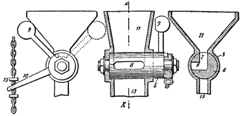
Fig. 11, 12, and 13. - DETAILS OF THE DICKERSON ACETYLENE APPARATUS
In this case, a charge of water fills the chamber 7 and 8 of the cock. This chamber may be oblong, as shown in Fig. 12, in order to increase its capacity. On the contrary, in the position of the counterpoise, 9, marked in continuous lines in Figs. 9 and 11, the channel, 8, communicates with the pipe, 13; the charge of water of chamber, 7 and 8, has fallen upon the carbides, but another quantity of water has not been able to enter, because the revolution of the cock has cut off all communication between the funnel, 11, and the generator, 4.
The acetylene produced by the reaction of the water upon the carbide raises the gasometer holder, which then actuates the plug, 6, of the cock, 5, and allows a new charge of water to enter the chambers, 7, 8. It is only when the holder descends anew to the position, 1, that the water in the chamber, 7, 8, can fall upon the carbide. The quantity of water that the cock is capable of containing is not sufficient to produce a quantity of gas exceeding the capacity of the gasometer, and, as it is impossible to introduce another quantity of water as long as the gasometer has not been emptied anew, any overproduction of gas is thus rendered impossible.
Fig. 10 applies to the introduction of the carbide into the water. It is necessary in this case that the carbide shall have been previously reduced to powder. The funnel, 11, is then closed by a cover, 21, in order to prevent any accidental escape of the gas. The carbide falls into the generator, the bottom of which is open. The latter enters a tank into which flows a current of water, escaping through the waste pipe, 19, in carrying along the lime formed. The height of the water in the tank is sufficient to furnish the pressure necessary to allow the gas to enter the gasometer through the pipe, 12.
Continue to:
My Books

