Machine Moulding Without Stripping Plates
Description
This section is from "Scientific American Supplement". Also available from Amazon: Scientific American Reference Book.
Machine Moulding Without Stripping Plates
By E. H. Mumford, Plainfleld, N.J.
(Member of the Society.)
Moulding machines may be classed under three heads. First, machines which only ram the moulds, and, when the ramming is done by means of a side lever, by hand, are generally called "squeezers." Second, machines which only draw the patterns, the ramming being accomplished by the usual hand methods. Third, machines which both ram the moulds and draw the patterns, ramming either by a hand-pulled lever or by fluid pressure on piston or plunger and drawing the patterns through a plate called a "stripping plate" or "drop plate" - till recently the usual method - or without the use of this plate fitting everywhere to pattern outline at the parting surface, the patterns being effectively machine guided in either case.
It is to the third class that the machine which is used to illustrate the subject of this paper belongs, and which would seem to have enough that is novel in the application of machinery to the foundry to merit the attention of the society.
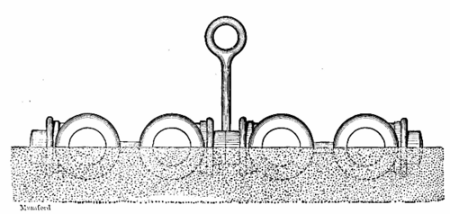
Fig. 1. - ORDINARY METHOD OF DRAWING PATTERN SPIKE AND RAPPER.
At the risk of appearing pedantic, but with a view to developing an appreciation of the true function of the method of pattern drawing used in this machine, attention is called to the following sectional views of moulds and ways of drawing patterns occurring in machine moulding. Fig. 1 shows an ordinary "gate" of fitting patterns being drawn from the drag or nowel part of the mould by means of a spike and rapper wielded by the moulder's hand after cope and drag have been rammed together on a "squeezer" and cope has been removed. Frequently the pernicious "swab" is used to soak and so strengthen joint outlines of the sand before drawing patterns, in such cases as this. In this case, before cope is lifted, these patterns must be vigorously rapped through the cope; an amount depending (and so does the size of the casting) upon the mood and strength of the moulder.
Fig. 2 shows the stripping or drop plate method of drawing patterns.

Fig. 2. - STRIPPING PLATE METHOD OF DRAWING PATTERNS.
In this method the patterns are not rapped at all and are drawn in a practically straight line so that the mould is absolutely pattern size.
The stripping plate is fitted accurately to every outline at the joint surface of the patterns, obviously at considerable expense, and, of course, at the instant of drawing the patterns, supports the joint surface of the mould entirely. This is, at first sight, an ideal method of drawing patterns, and it has for years been the only method practiced on machines. It has two disadvantages. The patterns are separated from the stripping plate by the necessary joint fissure between the two. Fine sand continually falls into this and, adhering to the joint surfaces more or less, grinds the fissure wider. This leads to a gradual reduction of size of patterns on vertical surfaces and a widening of the joint fissure often to such an extent that wire edges are formed on the mould, causing, on fine work, "crushing" and consequently dirty joints. A nicely fitted but worn plate of twenty-four pieces which had cost, at shop expense only, $250, was recently replaced by a plate of twenty-eight pieces, fitted ready for the machine under the new system about to be described, for not more than $25.
The stripping plate method has another drawback, not always appreciated, probably because accepted as inevitable. Stripping plate patterns are not rapped, and there frequently occur on surface of patterns, remote from the action of the stripping plate, rectangular corners just as important to mould sharply as those at the parting line. Such corners have either to be filleted or "stooled" in stripping plate work, and neither method often is practicable. When the entire pattern and plate are vibrated so that the corners where the pattern joins the plate draw perfectly, as they do in the machine to be described, it is obvious that similar corners anywhere on pattern surface will draw equally well.
The vibrating of patterns, or rather of moulds, during the operation of drawing the patterns possesses little of novelty. Ever since a bench moulder's neighbor first rapped the bench while he lifted a cope or drew a pattern, the thing has been done in one way or another. In fact, machines are now and then found on the market in which a device like a ratchet or other mechanical means for jarring the machine structure during pattern drawing renders the working of easy patterns without stripping plates possible.
The idea of applying a power driven vibrator directly to the plate carrying the patterns to thus vibrate them independently of other parts of the machine and the flask and sand has been the subject of the issue of patents to Mr. Harris Tabor, and the various figures shown will serve to illustrate the mechanism.
Briefly, the operation of the machine is as follows: The ramming head shown thrown back at the top of the machine is drawn into a vertical position after flask has been placed and filled with sand. The 3-way cock shown at the extreme left is then quickly opened, admitting compressed air of 70 to 80 pounds pressure to the inverted cylinder shown at the center of the cut. The cylinder, with the entire upper portion of the machine, is thus driven forcibly up against the ramming head, flask, sand and all. Often a single blow suffices to rain the mould - often the blow is quickly repeated, according to the demands of the particular mould in hand. Gravity returns the machine to its original position, as the 3-way cock opens to exhaust. After pushing the ramming head back and cutting sprue, if the half mould is cope, the operator seizes the lever shown just inside the 3-way cock at the right, and, drawing it forward and down, raises the outer frame of the top of machine containing the flask pins, with flask and sand thereon, away from the patterns, thus drawing them from the sand.
Just as he seizes the pattern drawing lever with his right hand, he presses with his left on the head of a compression valve shown at the left side of top of machine, thus admitting air to the pneumatic vibrator already referred to.
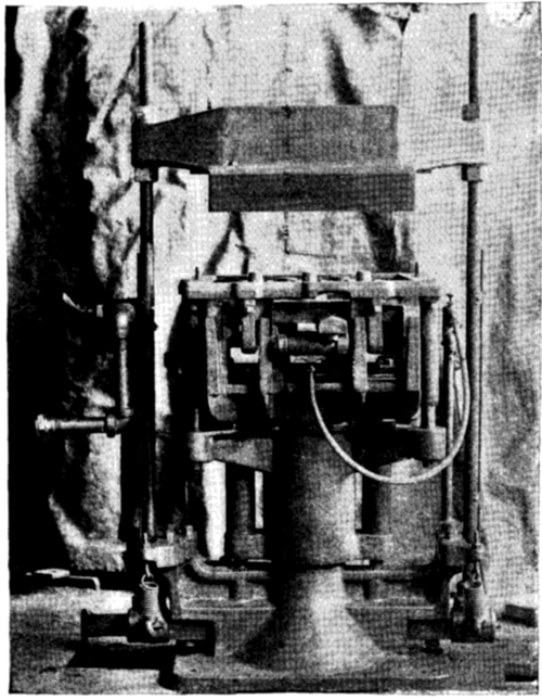
Fig. 3. - POWER DRIVEN VIBRATOR MACHINE.
Fig. 3, a rear view of the machine, shows at the top center, with its inlet hose hanging to it, this vibrator, which is shown in section in Fig. 4. It consists simply of a double acting elongated piston having a stroke of about 5/ inch in a valveless cylinder and impacting upon hardened anvils at either end at the estimated rate of 5,000 blows per minute.
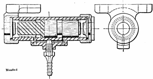
Fig. 4. - SECTION THROUGH VIBRATOR.
The method of communicating the rapid yet small oscillations of the vibrator to the patterns and yet keeping them from being transmitted to the rest of the mechanism is this:
A frame, called a vibrator frame, to which the pneumatic vibrator is bolted and keyed, is shown in Fig. 5. To this frame the plate carrying the patterns, often, in cases of patterns having irregular parting lines, forming one and the same casting with the patterns, is fastened by the four machine screws, the small tapped holes for which are shown in the corners. In fact, in changing patterns, the process consists of simply removing these four machine screws, taking up the pattern plate and screwing to the vibrator frame the new pattern plate. The vibrator frame itself is secured to the machine structure by the four larger bolts, the holes for which are shown in the inner corners. These bolts are, as shown in Fig. 7, surrounded by thick bushings. These bushings are elastic to such a degree as to absorb the sharp vibrations of vibrator frame and patterns, while so firm and well fitted as to hold patterns accurately to their position.
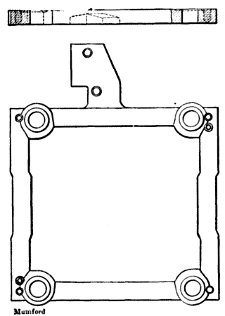
Fig. 5. - VIBRATOR FRAME.
The action of the vibrator is such as to give to the entire pattern surface an exceedingly violent shiver, making it impossible that any sand should adhere to this surface, while the magnitude of the actual movement of the pattern is so slight that it is found to fill the mould so completely that it is impracticable to draw it a second time without rapping. Yet, so truly are the patterns held and so little disturbed from their original position, that it is perfectly practicable to return patterns to a mould having the finest ornamental surface in the ordinary practice of "printing back."
In cases where deep pockets of hanging sand occur, which cannot be held during lifting off and rolling over, machines are arranged to roll the flask over in their operation and draw the patterns up under the influence of the pneumatic vibrator, though, owing to the time consumed in the rolling over process (and each operation counts in seconds on a moulding machine) this style of machine is not usually as rapid in its working as the simpler type, in which the flasks come off in the same way they go on.

Fig. 6. SET OF PATTERNS FITTED TO PLATES.
Fig. 6 shows a set of patterns as they are ordinarily fitted to plates for this machine. Round holes will be noticed at places in the plate surface. These are openings for the insertion of what are called "stools."
When it is found necessary to support the sand surface at any point, or generally, round holes are drilled through either plate or pattern surface and loose cylindrical pieces are dropped into these holes, their upper end surfaces being flush with the plate or pattern surface and their lower ends resting on the plate called, from this use, a stool plate. This plate appears in Fig. 7 at A and is hung solidly by the brackets shown at B from the frame which carries the flasks, so that it has the same upward motion as the flasks, and the upper ends of the stools remain in contact with the sand of the mould until same is lifted from machine. Fig. 7, showing a vertical section through a machine, will make perfectly clear the position and action of these stools.
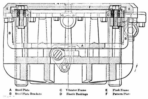
Fig. 7. VERTICAL SECTIONS FITTED TO PLATES.
As illustrating the importance of being able to work without stripping plates on a line of work which is much more extended than that possible with them, we may say that a machinist with a drill press supplied with split patterns and planed pattern plates has matched and fixed five sets of from four to eight pieces in a day: and wooden patterns fitted for temporary use in the same way are of frequent occurrence when it is not thought wise to go to the expense of metal patterns on account of the relatively small number of castings to be made from them.
It is not perhaps too much to say that pattern expense is not the final evil of the costly and not durable stripping plate patterns.
[1] Paper presented at the New York meeting (December, 1897) of the American Society of Mechanical Engineers, and forming part of volume xix. of the Transactions.
Continue to:
My Books

