The Two Or Three Phase Alternating Current Systems. Continued
Description
This section is from "Scientific American Supplement". Also available from Amazon: Scientific American Reference Book.
The Two Or Three Phase Alternating Current Systems. Continued

FIG. 4.

FIG. 5.
The two figures, 4 and 5 (or 7), correspond with each other in so far as the currents in the three leads, shown in heavy lines, have a phase between those of the two which compose them. Referring now to Fig. 6 (or 8), which is precisely like Fig. 5 (or 7), except that it has an additional winding shown in heavy lines, it will be seen that each of the three leads, shown in heavy lines, is wound around the armature before leaving it, forming an additional coil lying between the two coils with which it is in series. The phase of the heavy line currents was shown in Fig. 4 to lie between the other two. Therefore, in the armature in Fig. 6 (or 8) there will be six phases, while in Fig. 5 there are only three, the number of leads (three) remaining the same as before. This is the fundamental principle of this ingenious invention. To have six phases in Fig. 5 would require six leads, but in Fig. 6 precisely the same result is obtained with only three leads. In the same way the three leads in Fig. 6 might again be combined and passed around the armature again, and so on forming still more phases, without increasing the number of leads. Figs. 7 and 8 compound with 5 and 6 and show the same system for a Gramme ring instead of a cylinder armature.
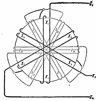
FIG. 6.

FIG. 7.

FIG. 8.
As was stated in the early part of this description, the main object in a rotary current motor is to have a magnetic field which is as nearly constant in intensity as possible, and which changes only its position, that is, its axis. But in Fig. 4 it was shown that the current I (in dotted lines) is greater than the others (about as 1.4 to 1 for a phase difference of 90 degrees). If therefore the coils in Fig. 6 or 8 were all alike, the magnetism generated by the heavy line coils would be greater than that generated by the others, and would therefore produce very undesirable pulsations in the magnetic fields; but as the magnetism depends on the ampere turns, it is necessary merely to have correspondingly fewer turns on these coils, as compared with the others. This is shown diagrammatically in Figs. 6 and 8, in which the heavy line coils have less windings than the others. In practice it is not always possible to obtain the exact ratio of 1 to 1.4, for instance, but even if this ratio is obtained only approximately, it nevertheless reduces the pulsations very materially below what they would be with half the number of phases.
It is therefore not necessary in practice to have more than an approximation to the exact conditions.
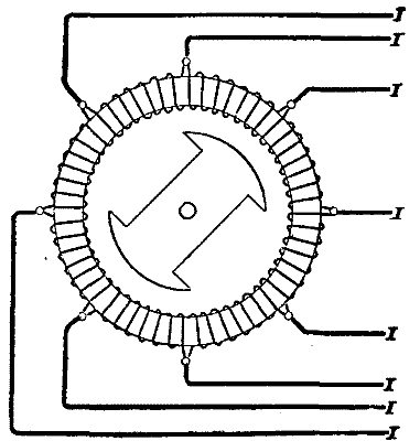
FIG. 9.

FIG. 10.

FIG. 11.

FIG. 12.
Fig. 9 shows a multiple phase armature having double the number of phases as Fig. 1, and would according to the old system, therefore, require eight leads. Fig. 10 shows the new system with the same number of phases as in Fig. 9, but requiring only four leads instead of eight. Figs. 11 and 12 correspond with Figs. 7 and 8 and show the windings for a multipolar motor in the two systems.
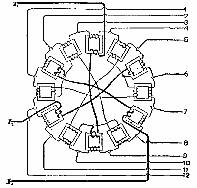
FIG. 13.

FIG. 14.

FIG. 15.
These figures show how a motor may be wound so as to be a multiple phase motor, although the current entering the motor is a simple, elementary three or two phase current, which can be transformed by means of a simple three or two phase current transformer, before entering the motor, such transformers as are used at present in the Lauffen-Frankfort transmission. But the same principle as that for the motor may also be applied to transformers themselves, as shown in Figs. 13 and 14. Fig. 13 shows a set of transformers which are fed by a simple three-phase current shown in heavy lines, and which gives in its secondary circuit a multiple phase rotary current. The connections for the primary circuit of a transformer with six coils are shown diagrammatically in Fig. 15, the numbers 1 to 6 representing the succession of the phases. Fig. 14 shows a transformer for a two-phase current with four leads, transforming into a multiple phase current of 16 leads. The transformer in this figure is a single "interlocked" transformer in which the fields are magnetically connected and not independent of each other as in Fig. 13. This has advantages in the regulation of currents, which do not exist in Fig. 13, but which need not be entered into here.
The transformers used in the Lauffen-Frankfort transmission are similar, magnetically, to Fig. 14, only that they are for a simple three-phase current in both primary and secondary circuits. Attention is also called to the difference in the connections of secondary circuits in Figs. 13 and 14; in the former they are connected in a closed circuit similarly to an ordinary closed circuit armature, while in Fig. 14 they are independent as far as the currents themselves are concerned, though magnetically their cores are connected. It is not the intention to enter into a discussion of the relative values of these various connections, but merely to draw attention to the wide range of the number of combinations which this system admits of. - Electrical World.
Continue to:
My Books

