Sensory Threshold for Electric Shock. Part 2
Description
This section is from the book "Human Vitality And Efficiency Under Prolonged Restricted Diet", by Francis G.BENEDICT, Walter R. Miles, Paul Roth, And H. Monmouth Smith. Also available from Amazon: Human Vitality and Efficiency Under Prolonged Restricted Diet.
Sensory Threshold for Electric Shock. Part 2
In any such arrangement of apparatus the device used to make and break the circuit and to determine the length of the shock is of critical importance. The particular device constructed at the Nutrition Laboratory for this purpose was a modification of a similar instrument designed by the late Keith Lucas and used by him in his extraordinary researches on muscle and nerve excitation.1 According to illustrations and description, in the case of the Lucas pendulum the contact key had to be set and the pendulum adjusted and released by hand for each stimulation delivered to the nerve or muscle preparation. It was necessary to arrange for these factors to be automatically taken care of in our instrument, the general plan of which is shown in figure 44. Pttpendicular to a heavy wooden base B, a short stud T was rigidly mounted. About this an eccentric weight E was mounted on ball bearings so that it could revolve freely. A light aluminum arm A, fastened to the eccentric, extended from the axis of rotation a distance of 25 cm. This arm resting against a suitable catch C held the eccentric in a position above its center of gravity and ready to be tipped over to the left by the offset 0 carried by the wheel W. When the eccentric was lifted from the catch C, and pushed slightly past its highest position by 0, which moved from right to left, it then fell of its own accord and with a very swift movement, opened the two switches S and S', and carried through to the catch C. The contacts at S and S' were so devised that when struck open they remained in this position unless released by pressure from the feet F and F' carried by the wheel W. The contact S was closed by the foot F and was always closed before S' so as to reestablish the short circuit P, figure 43. The contacts were thus closed and in proper position before the offset 0 picked up the arm of the eccentric at the beginning of its second revolution. The wheel W was driven from a variable-speed, worm-gear motor M, which was arranged to run silently. The contact S had a permanent mounting. S' was mounted on a metal disk D. This also carried a scale giving degrees, and moved about the axis of the stud T. It was kept in position and could be clamped by the lugs L and L and moved conveniently by the handle H. The position of this movable disk determined the distance between the contacts S and S', and thus the duration of the electric shock. A hard block of insulating material I, mounted on the arm A, provided against electrical connections between the two contacts when the pendulum should swing past them. A pointer at P, secured to the arc K, indicated the degrees of separation between the switches.

Fig. 43. - Schematic diagram of circuit for measuring the electrical threshold.
D, drop wire; V, voltmeter of standard make; R, 200,000 ohms resistance; C, control switch; E, non-polarizable electrodes; F, fingers of subject to be stimulated; S and S', switches to be opened in turn by a swiftly moving pendulum represented by the arrow, A; P and P', parallel paths for current when S and S' are closed.

Fig. 44. - Diagram of the automatic pendulum key used to regulate the length of the electric shocks employed as stimuli.
T, a rigid stud (mounted in the heavy base, B) about which the eccentric, E, bearing the extension arm, A may revolve; M, a worm-gear motor revolves wheel, W, from right to left, and the offset, 0, carries the arm, A, from its position of rest, causing it to fall to the left; S and S', two switches opened by A; C, catch device for retaining A after its fall; F and F', feet mounted on W and used to close switches, S and S', respectively, preparatory to the next shock; J, insulation material on the arm, A; S' is mounted on the large disk, D, which is movable by the handle, H. By the scale and pointer, P, mounted on the arc, K, the switches may be set to certain degrees of separation and the disk clamped by lugs, L. The relative size of the instrument may be gaged by the size of the disk, D, which is 46 cm. in diameter.
The essential detail of one of the contacts opened by the moving pendulum is made clear in figure 45, which is a drawing of the back of S in figure 44. The block of rubber R, about which the contact device is built, is 33 mm. square and 26 mm. thick (vertical direction in the figure). In mounting it is secured to a metal plate m by posts and nuts n and n'. The two parts of the contact, a and b, are shown at the left. Only the binding-post for b is visible in the drawing; this is at the extreme right, a, the movable part which is struck back by the arm of the pendulum is held in metal supports at x and y. Good electrical connection with this moving portion is assured by the spring I, which also normally serves to hold the contact surface of a against that of b.A steel spring is os located and held in definite position by pointed screws, which press into appropriate openings at one end, that when a is moved forward by the pendulum it can not return into contact with b, as would naturally be caused by the spring l, since a is caught on the detent d of the spring s in the position shown in the figure. It is retained here out of contact with b until the foot / passes over the plunger p, depressing the spring a and releasing a, so that it reestablishes good contact with 6. The apparatus is arranged so that the contact between a and 6 is made in the switch S some time before the contact is reestablished in switch S' (fig. 44). This precaution insures that when the switches are close together, that is, when a short-duration interval is used for the electric shock, the unavoidable chatter at reestablishment of contact in the switch S will not cause extra shocks to reach the tissue under examination.
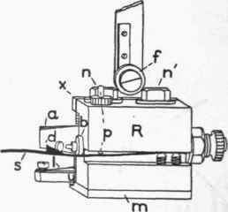
Fig. 45. - Detail for one of the contact devices struck open by the pendulum.
R, rubber block 33 mm. square and 26 mm. thick; m, metal base for securing block by posts and nuts, n and n'; b, fixed part of contact; a, movable portion of contact fastened in metal parts, x and y; s, spring with detent, d, to catch and hold a after it is struck back from b by pendulum; f, a foot which depresses plunger, p, which in turn depresses d, allowing a under the impulse of the spring I to return into contact with b ready for the next pendulum stroke.
Continue to:
My Books

