The Treadmill Chamber
Description
This section is from the book "Human Vitality And Efficiency Under Prolonged Restricted Diet", by Francis G.BENEDICT, Walter R. Miles, Paul Roth, And H. Monmouth Smith. Also available from Amazon: Human Vitality and Efficiency Under Prolonged Restricted Diet.
The Treadmill Chamber
The treadmill chamber was, for convenience in handling, constructed in three parts; the base A, the skirt B, and the cover C. These parts were made of Nos. 24 and 28 galvanized sheet iron.
The sheet iron base, A, was formed over a platform 12.5 cm. high, 223 cm. long, and 88 cm. wide, made of spruce strips and matched floor boards to give the necessary support and rigidity for the heavy mill. The edge of the base was shaped into a trough, a, 4 cm. wide and 8 cm. deep, which was filled with a light non-viscous oil. The skirt, B, fitted into this trough and the oil made an air-tight seal between the base and the skirt.
The skirt, B, was of such a shape that it fitted rather snugly over the mill, having a clearance of 6 cm. at the ends and 5 cm. at the sides, and rising towards the center in the general form of a blunt wedge with an opening at a height of 62 cm. above the leather belt. The upper opening of the skirt was approximately 81 cm. square and was shaped with a trough 6 cm. deep and 4 cm. wide, thus forming a second seal (6) similar to that of the base; into this the cover (C) fitted. The seal b was filled with water, for if oil were used the frequent raising and lowering of the cover and consequent drip from the edges would make it difficult to keep the apparatus clean. On the other hand, when the skirt was once put in place in the oil seal a of the base, it was not necessary to disturb it except to get at the lower part of the mill for oiling or for attention to the motor.
1 Benedict and Murschhauser, Carnegie Inst. Wash. Pub. No. 231, 1915, p. 34.
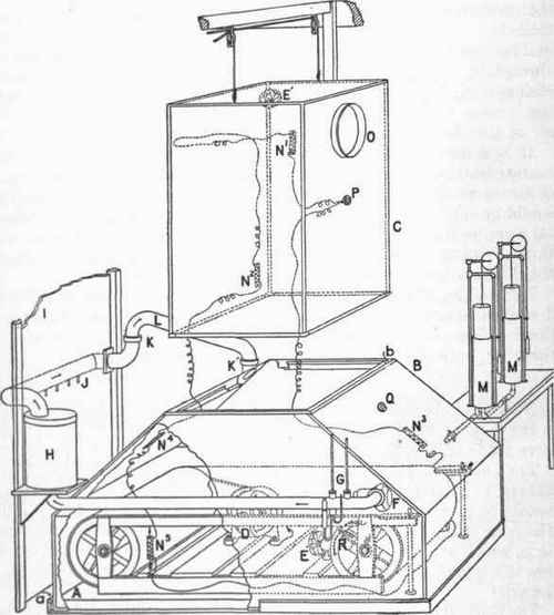
Fig. 14. - The treadmill chamber.
The treadmill rests on the base A, which has an oil seal, a, into which the skirt B fits. The subject stepped over the side of the skirt on to the treadmill and the cover, C, was lowered into the water seal, b, of the skirt. The treadmill was driven by the motor D, controlled by resistances not shown in the figure. Fans E and E' stirred the air and a blower, F, forced the air past the psychrometcr, O, through the drier H. From H, the pipe went through a partition, J, into an adjoining room where samples of air were drawn at J for analysis. The air returned to the chamber through L, which was removable at the water seals K and K'. M, the tension equaliser or spirometer connected to a reserve spirometer M'. N1 N2, N3, N4, and N5, resistance thermometers in series; a sixth one is not shown in the figure. 0, window; P, electrical plug for temperature and pulse leads. Q, electrical plug for distance and step counters. R, electrical contact for recording revolutions of front pulley.
The cover, C, was prism-shaped, 134 cm. high and 79 cm. square on its base, which fitted into the seal of the skirt. It was counterpoised over pulleys on the ceiling and could be easily raised from the seal, giving a clearance above the skirt of 66 cm. A circular plate glass window, 0, 25 cm. in diameter, was inserted in the front of the cover.
In addition to these main features there were the following accessory parts:
Air-drier (H) and psychrometer (G); tension equalizers (M and M'); resistance thermometers (Nl to N5); barometer; and gas-analysis apparatus.
Continue to:
My Books

