Boring-Bar With Provision For Cutting Lubricant
Description
This section is from the book "Boring, Recessing And Multiple Turning Tools", by Albert A. Dowd. Also available from Amazon: Boring, recessing and multiple turning tools.
Boring-Bar With Provision For Cutting Lubricant
On certain classes of work it is very difficult to supply the cutting points of the tools with sufficient lubrication to make them thor-ouhgly efficient, when the regular supply system is used. Some method must be devised, therefore, to direct the flow to the point or points where the cutting action takes place. An example of a bar arranged to carry the lubricant to inaccessible tools is shown in the upper part of Fig. 5. The work A in the chuck jaws is an automobile hub of malleable iron. It will be noted that the portion bored by the forward tool C is in such a position that it cannot be reached for lubricating purposes in the ordinary way, but the rear tool D can easily be taken care of. The boring-bar B is of a low grade of tool steel and fits the turret hole at the rear end; the forward end J is a running fit in the chuck bushing L. A telescoping oil supply tube K enters this end of the bar and is supplied with lubricant from the rear end of the spindle. The hole in the bar at H leads the fluid directly onto the face of the cutting tool C, thus insuring constant lubrication at this point. The two tools are held in place by the screws E and F, and they are provided with means of adjustment in the backing-up screws G. The writer has used bars of this type in a number of cases with very gratifying results.
Fig. 5 (lower illustration) shows a very different condition, in a multi-cutting boring-bar for generating a series of true holes in the bronze artillery hub A. The finished hole is tapered but a starting bar was used in order to prepare the hole properly for the taper tools which followed it, so that they would not be influenced by the irregularities of the cored hole. In this case the turret lathe was one of the flat-turret variety, and provision was made for lubrication through the hole C in the turret face. As the turret indexed to the proper position, this hole came directly over another in the slide, which, in turn, was connected with the lubricant pressure supply system, thus allowing the liquid to pass up into the body of the tool-holder. The boring-bar G is turned down at the rear end to fit the tool-holder B, and has an annular groove E which is packed with felt to prevent the escape of lubricant. A shoe D is forced down on the bar by the two screws K and prevents the bar from turning. The hole H in the bar is drilled from the forward end and is tightly plugged so that this end remains closed to prevent the lubricant from passing through. A groove is cut in front of the tools J, M and L, as shown at J, and this allows the fluid to flow directly onto the faces of the tools. The end of the bar is piloted at 0 in the bushing N which is fixed in the chuck body. An arrangement of this sort has also proved successful in a number of instances.
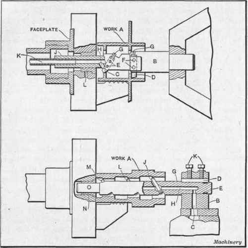
Fig. 5. Boring-bars arranged for lubricating Cutters.
Continue to:
My Books

