207. - Force Diagram For Truss In Fig 61
Description
This section is from the book "The American House Carpenter", by R. G. Hatfield. Also available from Amazon: The American House Carpenter.
207. - Force Diagram For Truss In Fig 61
For this truss we have, in Fig. 72, a similar design, properly prepared by weights and lettering; and in Fig. 73 the force diagram appropriate to it.
In the construction of this diagram, proceed as directed in the previous example, by first constructing N S, the vertical line of weights; in which line NO,OP,PQ,QX, and R S are made respectively equal to the several weights above the truss in Fig. 72. Then divide NS into two equal parts at T. Make TKand TL each equal to the half of the weight K L. Make J K and L M equal to the weights J K and L M of Fig. 72. Now, since MN is equal to one half of the weights above the truss plus one half of the weights below the truss, or half of the whole weight, it is therefore the weight upon the support N (Fig. 72), and represents the reaction of that support. A horizontal line drawn from M will meet the inclined line drawn from N, parallel with the rafter A N (Fig. 72), in the points,and the three sides of the triangle AMN,Fig. 73, will give the strains in the three corresponding lines meeting at the point A MN, Fig. 72. The sides of the triangle HJ S, Fig.
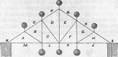
Fig. 72.
73, give likewise the strains in the three corresponding lines meeting at the point H JS, Fig. 72. Continuing the construction, draw all the other lines of the force diagram parallel with the corresponding lines of Fig. 72, and as directed in Art. 195. The completed diagram will measure the strains in all the lines of Fig. 72.

Fig. 73.
208. - Force Diagram for Trudd in Fig. 63. - The roof truss indicated at Fig. 63 is repeated in Fig. 74, with the addition of the lettering required for the construction of the force diagram, Fig. 75.
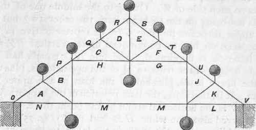
Fig. 74.
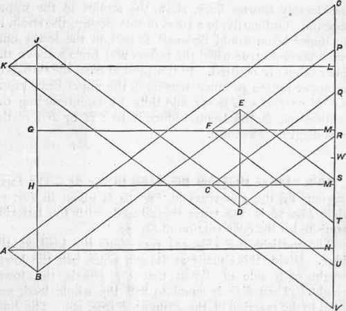
Fig. 75.
In this case there are seven weights, or loads, above the truss, and three below. Divide the vertical line O V at W into two equal parts, and place the lower loads in two equal parts on each side of W. Owing to the middle one of these loads not being on the tie-beam with the other two, but on the upper tie-beam, the line G H, its representative in the force diagram, has to be removed to the vertical BJ, and the letter M is duplicated. The line NO equals half the whole weight of the truss, or 3 1/2 of the upper loads, plus one of the lower loads, plus half of the load at the upper tie-beam. It is, therefore, the true reaction of the support NO, and A N is the horizontal strain in the beam there. It will be observed also that while HM and G M (Fig. 75), which are equal lines, show the strain in the lower tie-beam at the middle of the truss, the lines C H and FG, also equal but considerably shorter lines, show the strains in the upper tie-beam. Ordinarily, in a truss of this design, the strain in the upper beam would be equal to that in the lower one, which becomes true when the rafters and braces above the upper beam are omitted. In the present case, the thrusts of the upper rafters produce tension in the upper beam equal to CM or FM of Fig. 75, and thus, by counteracting the compression in the beam, reduce it to CH or FG of the force diagram, as shown.
209. - Force Diagram for Truss in Fig. 64. - The force diagram for the roof-truss at Fig. 64 is given in Fig. 77, while Fig. 78 is the truss reproduced, with the lettering requisite for the construction of Fig. 77.
The vertical EF (Fig. yy) represents the load at the ridge. Divide this equally at W, and place half the lower weight each side of W, so that CD equals the lower weight. Then ED is equal to half the whole load, and equal to the reaction of the support E (Fig. 76). The lines in the triangle A D E give the strains in the corresponding lines converging at the point A D E of Fig. 76. The other lines, according to the lettering, give the strains in the corresponding lines of the truss. (See Art. 195.)
210. - Force Diagram for Truss in Fig. 65. - This truss is reproduced in Fig. 78, with the letters proper for use in the force diagram, Fig. 79.
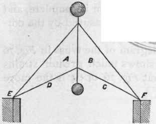
Fig. 76.
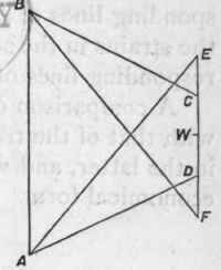
Fig. 77.
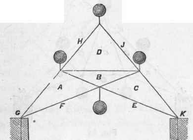
Fig. 78.
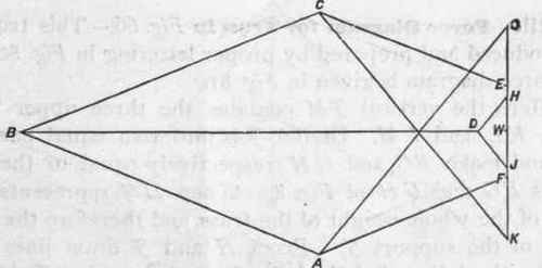
Fig. 79.
Here the vertical G K, containing the three upper loads GH, HJ, and JK, is divided equally at W, and the lower load E F is placed half on each side of W, and extends from E to F. Then FG represents one half of the whole load of the truss, and therefore the reaction of the support G (Fig. 78). Drawing the several lines of Fig. 79 parallel with the corresponding lines of Fig. 78, the force diagram is complete, and the strains in the several lines of 78 are measured by the corresponding lines of 79. (See Art. 195.)
A comparison of the force diagram of the truss in Fig. 76 with that of the truss in Fig. 78 shows much greater strains in the latter, and we thus see that Fig. 76 or 64 is the more economical form.
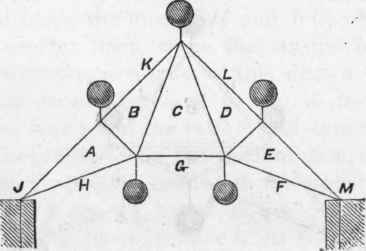
Fig. 80.
211. - Force Diagram for Truss in Fig. 66. - This truss is reproduced and prepared by proper lettering in Fig. 80, and its force diagram is given in Fig. 81.
Here the vertical JM contains the three upper loads JK, KL, and LM. Divide JM into two equal parts at G, and make FG and GH respectively equal to the two loads FG and GH of Fig. 80. Then HJ represents one half of the whole weight of the truss, and therefore the reaction of the support J. From H and J draw lines parallel with A H and A J of Fig. 80, and the sides of the triangle A H J will give the strains in the three lines concentrating in the point A H J (Fig. 80). The other lines of Fig.
81 are all drawn parallel with their corresponding lines in Fig. 80, as indicated by the lettering. (See Art. 195.)
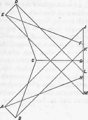
Fig. 81.
Effect Of Elevating The Tie-Beam
212. - Roof-Truss: Effect of Elevating the Tie-Beam. - From Arts. 670, 671, Transverse Strains, it appears that the effect of substituting inclined ties for the horizontal tie at feet of rafters is -
V = P a/b (91.)
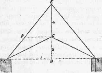
Fig. 82
in which P represents half the weight of the whole truss and the load upon it; a + b = height of the truss at middle above a horizontal line drawn at the feet of the rafters; a equals the height from this line to the point where the two inclined ties meet; b, the height thence to the top of the truss; and V, the additional vertical strain at the middle of the truss due to elevating the tie from a horizontal line.
Examples are given to show that when the elevation of the tie equals 1/4 of the whole height, the vertical strain thereby induced is equal to a weight which equals 1/3 of half the whole load; and that when the elevation equals half the whole height, the vertical strain is equal to half the whole load. This is the strain in the vertical rod at middle. The strains in the rafters and inclined ties are proportionately increased.
Continue to:
My Books

