272. - Railing For Platform Stairs Where The Rake Meets The Level
Description
This section is from the book "The American House Carpenter", by R. G. Hatfield. Also available from Amazon: The American House Carpenter.
272. - Railing For Platform Stairs Where The Rake Meets The Level
In Fig. 150, abc is the plan of a line passing through the centre of the rail around the cylinder as before, and je is a vertical section of two steps starting from the floor, hg. Bisect eh in d, and through d draw df parallel to hg; bisect fn in l, and from l draw It parallel to nj; from n draw nt at right angles to jn; on the line ob make ot equal to nt. Then, to obtain a mould for the twist going up the flight, proceed as at Fig. 145; making ec in that figure equal to en in Fig. 150, and the other lines of a length and position such as is indicated by the letters of reference in each figure. To obtain the mould for the level rail, extend bo (Fig. 150) to i; make oi equal to fl, and join i and c; make ci (Fig. 151) equal to ciat Fig. 150; through c draw cd at right angles to c i; make dc equal to df at Fig. 150, and complete the parallelogram odci; then proceed as in the previous cases to find the mould.
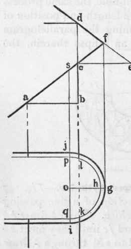
Fig. 149.
Hand-Rail At Rake And Level

Fig. 150.
Fig. 151.
Continue to:
My Books

