Moment Of Inertia. Continued
Description
This section is from the book "The Building Trades Pocketbook", by International Correspondence Schools. Also available from Amazon: Building Trades Pocketbook: a Handy Manual of reference on Building Construction.
Moment Of Inertia. Continued
Examfle
The moment of inertia of the section shown in Fig. 4 may he found as follows, the figure being redrawn with the neutral axis located by the distance c, obtained from calculations on page 77, and shown in Fig. 7.
Solution
First work out the formula ad2 + i for each elementary section, as in the follow-ing table.
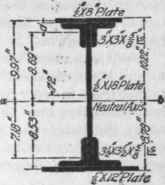
Fig. 7.
Elementary Section. | Area a. Sq. In. | d. In. | d2. | i. | ad2 + i. |
Upper plate .......... | 4.00 | 9.97 | 99.4 | *0833 | 397.68 |
2 upper angles...... | †3.56X2 | 8.69 | 75.51 | †3.20X2 | 544.03 |
Web-plate............. | 9.00 | .72 | .5184 | 243.00 | 247.66 |
2 lower angles....... | 3.98X2 | 7.18 | 51.55 | 4.33X2 | 418.99 |
Lower plate.......... | 6.00 | 8.53 | 72.76 | .125 | 436.68 |
Moment of inertia of section, I = Σ(ad2 + i) = 2,045.04.
Graphical Method
The location of the neutral axis and the moment of inertia of any section may be obtained by the following graphical method, which is sufficiently accurate for all practical purposes.
Example
Locate the neutral axis, and find the moment of inertia of the section shown at (a), Fig. 8.
Solution
First, draw the section, either full size or to any scale, as at (a).
* Figured by formula bd3 / 12, on page 83.
†See page 85.
Second, divide this section by horizontal lines into strips of equal or unequal height; find the area in square inches and the center of gravity of each strip; since the strips in this case are rectangles, the centers of gravity will be at the centers of the strips, through which points dot-and-dash lines have been drawn.
Third, on any horizontal line lay off, from left to right, to any scale, distances proportional to the area of the strips, taking them in order from top to bottom of the section. This horizontal line may be called the load or area line. Thus, at (b), the distances AB,BC, CD, etc. are measured to a scale of, say, 1/16 in. to 1 sq. in. area, and represent the areas of the sections P, Q, R, etc., respectively, in (a).

FIG.8.
Fourth, from the ends A and M of this line, draw lines inclined 45° to it, and intersecting at a point N called the pole. Draw lines from N to points B, C, D, etc.
Fifth, commencing anywhere on a horizontal line through the top of the section, draw the line 1-2 parallel with the 46° line A N; from the intersection of this line with one through the center of gravity of slice P, draw 2-3 parallel with BN; fan the intersection of 2-3 with the horizontal line passing through the center of gravity of slice Q, draw the line 3-4, parallel to Continue in this manner, drawing the remaining lines 4-5, 5-6, etc., parallel, respectively, to D N,. E N. etc.
Sixth, draw, from the points 1 and 11 at the end of the curve, 45° lines intersecting at the point 12, through which draw a horizontal line, cutting the section as shown at (a), Fig. 8; this line will be the neutral axis of the figure.
Seventh, the moment of inertia I may be found by multiplying the area * in square inches of the section-lined figure by the entire area of the section. Thus, if in this case the area of the former is 4.67 sq. in., and that of the section at (a) is 16.25 sq. in., the moment of inertia will be equal to 16.25 sq. in. X 4.67 sq. in. = 75.88, the value of I for this section.
Continue to:
My Books

