305. General Principles
Description
This section is from the book "Cyclopedia Of Architecture, Carpentry, And Building", by James C. et al. Also available from Amazon: Cyclopedia Of Architecture, Carpentry And Building.
305. General Principles
The practical applications of the principles of reinforced concrete which have already been discussed, have been almost exclusively those required for sustaining vertical loads; but a structure consisting simply of beams, girders, slabs, and columns may fall down, like a house of cards, unless it is provided with lateral bracing to withstand wind pressure and any lateral forces tending to turn it over. The necessary provision for such stresses is usually made by placing brackets in the angles between posts and girders, as has been illustrated in Fig. 102. These brackets are reinforced with bars which will resist any tensile stress on the brackets. The compressive strength of concrete may be relied on to resist a tendency to crush the brackets by compression. Usually such brackets will occur in pairs at each end of a beam supported on two columns. If we consider that any given moment is to be divided equally between two brackets, then, if we are to have a working tension of 15,000 pounds per square inch in the steel, and a working compression of 500 pounds per square inch in the concrete, the area of the concrete must be 30 times the area of the steel. But since the outer face of the concrete will have practically twice the compression of the concrete at the angle of the beam and column, and since the maximum of 500 pounds per square inch must not be exceeded, we must have twice that area of concrete; or, in other words, the area of the concrete from the point of the angle down to the face must be 00 times the area of the steel.
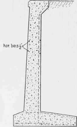
Fig. 114. L-Shaped Retaining Wall.
Although these brackets are frequently put in without any definite design, it is possible to make some sort of computation, especially when a building is directly exposed to wind pressure, by computing the moment of the wind pressure. For example, if a building is 100 feet long and 50 feet high, and is subjected to a wind pressure of 30 pounds per square foot, the total wind pressure will be 50 X 100 X 30 = 150,000 pounds. Considering the center of pressure as applied at half the height, this would give a moment about the base of the building, of 150,000 X 25 = 3,750,000 foot-pounds = 45,000,-000 inch-pounds. If this 100-foot building had eight lines of columns with a pair of brackets on each line, and was four stories high, there would be 64 such brackets to resist wind pressure. Each bracket would therefore be required to resist 1/64 of 45,000,000 inch-pounds, or about 700,000 inch-pounds. We shall assume that the bracket will have a depth of 25 inches, from the intersection of the center lines of the column and the beam to the steel near the face of the bracket. Then, since each bracket must withstand a moment of 700,000 inch-pounds, the stress in the steel will be 700,000 ÷ 25 = 28,000 pounds. If the actual stress in the steel is 15,000 pounds per square inch, this would require 1.87 square inches of steel, which would be more than supplied by four 3/4 inch square bars. If these brackets were 12 inches wide and 25 inches deep, the area of concrete is 300 square inches, which is 160 times the area of the steel. There is, therefore, an ample amount of concrete to withstand compression, on the part of those brackets which are subject to compression rather than tension. It is probable that the above calculation is excessive on the side of safety, since it is quite improbable that such a broad area would ever be subject to a pressure of 30 pounds per square foot over the whole area. The method of calculation also ignores the fact that the monolithic character of a reinforced-concrete structure furnishes a very considerable resistance at the junction of columns and girders, and that they should not by any means be considered as if they were pin-connected structures, which would require that the whole of the lateral stiffening should be supplied by these brackets. Nevertheless these brackets must be designed according to some such method.
Continue to:
My Books

