Use Of Tables. Part 4
Description
This section is from the book "Cyclopedia Of Architecture, Carpentry, And Building", by James C. et al. Also available from Amazon: Cyclopedia Of Architecture, Carpentry And Building.
Use Of Tables. Part 4
These different functions can all be calculated quite readily, and it is important that the student should understand how these are obtained. For this purpose the functions of a 24-inch 80-lb. beam will be worked out. The section of the beam is here shown.

BEAM SECTION.
Area. Web = (24 - 2.284) X .50 =10.858
Flanges = 1.142 +.60 x 3.25 x 4 = 11.323
1.142 x .50 x 2 = 1.142 12.465
23.323
It will be noticed that the areas of fillets and the roundings of outer edges are disregarded. These closely offset each other.
Weight per Foot.
Since a cubic foot of steel weighs 490 lbs., the weight per foot of a 24-inch beam should be:
23.323 x12 x 490 = 79.331 lbs. 1,728
Moment of Inertia About Axis 1 - 1.
I of web (taken to outside of flanges) =1/12 x 1/2 x 243 = 576. I' of flange about an axis through center of gravity of each component element.
Axis A A = 1/12 X 3.25 X .603 X 4 = .234
Axis B B = 1/36 3.25 (1.142 - .60)3 = .057
.291
I of flanges about axis 1 - 1 = I' + A x 4d2.
Where A = area of flanges, and d = distance from center of gravity of flange to axis 1 - 1, as in the above, the flanges being divided into two figures, the d in each case will be the distance from 1 - 1 to the center of gravity of that figure.
I = 3.25 x .60 X H.702 x 4 = 1,067.752
3.25 X .271 X 11.222 x 4 = 443.505 1,511.548
576.
2,087.548
Table VI. Properties Of Channels

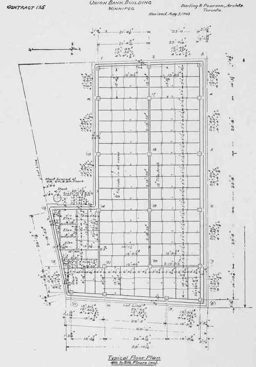
ONION BANK BUILDING, WINNIPEG, MANITOBA, CANADA.
Darling &. Pearson, Architects, Toronto; E. C. & R. M. Shankland, Engineers, Chicago
Typical floor-plan of steel construction. See also illustrations on page 58.
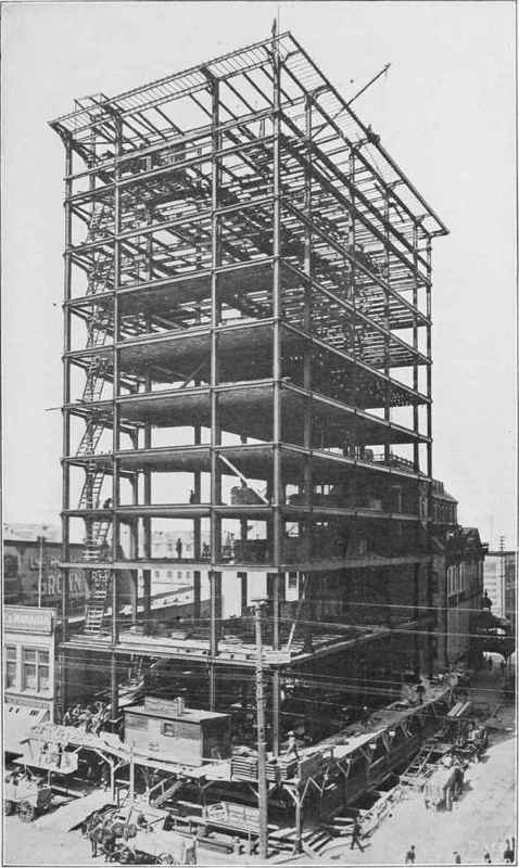
UNION BANK BUILDING, WINNIPEG, MANITOBA, CANADA.
View taken May 14,1904, seven and one-half months after work of excavation was started. Note the method of providing supports for the terra-cotta cornice which is hung from the steel work. See also illustrations on page 58.
Moment of Inertia about Axis 2 - 2.
For axis 2-2 = + 3.25 X .60 X (1.623 + .25 )2 X 4 = 27.362
Flange axis B' B' =1/36 x .542 X 3.253 X 4 = 2.060
For axis 2-2 = + .542 X 1.63 X (1.08 +-25)2 X 4 = 6.250 42.538 / 42.788
Other methods of computing the moments of inertia would perhaps bring a result even closer to the values given in the tables, which are taken from the Carnegie Handbook, although the values vary a little in the different books for identical sections.
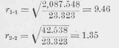
Radius of Gyration. By definition, the radius of gyration is equal to the square root of the quotient of the moment of inertia divided by the area of the section; therefore, if r1-1 and r2_2 correspond to radii of gyration about the axes 1-1 and 2-2 respectively,
Section Modulus. In the calculation of stresses in beams, the formula used is:
M = fI; y or, M = I f y.
The proper section of beam could be determined by this formula, using the moment of inertia, the distance from the neutral axis to the extreme fibre, and the allowable fibre stress. It is more convenient, however, to have the constant 1/y expressed in the tables, and this constant is called the "Section Modulus." In the above case, therefore,
S1-1= I = 2,087.548 = 173.96 y 12
Table VII. Properties Of Standard And Special Angles
Angles with Equal Legs.


Angles marked * are special,
Table VII. - (Concluded.) Properties Of Standard And Special Anglos
Angles with Equal Legs.

Angles marked * are special.
The section modulus about the axis 2-2 is not given in the tables, because the beam is rarely used in this position. It can, however, be readily obtained:
42.538 = 12.15
Coefficient of Strength. This also is a constant employed to express the relations of certain values used in the calculation of stresses in beams. As stated before, M = fI/y
Also M = 1/5 pl2 for a load uniformly distributed, where p = the load per linear foot, and I = the length of span in feet. As the value of M in the first equation is in inch-pounds, in the second also it must be in inch-pounds in order to equate them.
Therefore, M =fI/y = 12 pl2/8, and 8M/12 = pl2 = C; also, 8fI/12y = pl2 = C.
This value of C is convenient to use, because from it the total load that a beam can safely carry on a given span is readily obtained.
L = total load = pl = C/l.
To derive the value of C in the case of the beam above, if we use f = 16,000, which is the value for buildings, then
C = 8 X 16,000 X 2,087.548 12 X 12
= 1,855,598.
If the value of I given in the table of Carnegie's Handbook be used, the value of C will check with that above.
The value of C, however, varies as much as or more than this in the different books, because a slight variation in I is multiplied to such an extent. The variation, however, is of no practical importance in deducing the value of L, as the variation here is slight.
C', the coefficient derived by using the value of f= 12,500, becomes
C' = 8 X 12,500 X 2,087.548 / 12x12 = 1,449,685.
Equal Radii of Gyration. The last column in the table is very useful in the designing of members that are desired to be equally strong against bending both in the directon of the web and in a direction at right angles to it, as this column gives the distance apart that beams must be spaced to accomplish this result.
Continue to:
My Books

