Air-Currents And Air-Inlets. Continued
Description
This section is from the book "The Principles And Practice Of Modern House-Construction", by G. Lister Sutcliffe. Also available from Amazon: How Your House Works: A Visual Guide to Understanding & Maintaining Your Home.
Air-Currents And Air-Inlets. Continued
The market is so full of all kinds of appliances called "Ventilators", that difficulty In selection is experienced by those who have not a clear conception of what is required, or of what is possible of accomplishment thereby. The evil is, that so many people have a vague idea, fostered by the claims of rival manufacturers, that, when ventilators are once fixed, constant and com-fortable ventilation can be secured without further personal attention. If it be clearly understood that such is impracticable, then their employment will not be disontinued, but they will be used with greater discrimination and regulated to suit the varying changes of weather.
The simplest form of air-inlet is the "Sher-ingham" (Fig. 568), which necessitates a hole through an outer wall with a grating on the outside, and an inner frame provided with a hinged hopper-shaped flap, weighted so that when a weight attached to a cord is raised, the flap may be opened at will; this- is an useful appliance when suitably placed and regulated, but, as ordinarily used, too small and consequently liable to cause draughts.
Fig. 569 - is similar to a "Sheringham", but made larger and provided with a pierced inlet-plats, which has the effect of causing a better distribution of the incoming air.
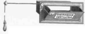
Fig. 563 - "sheringham" Air-inlet.
Fig. 570 shows a Sheringham air-inlet, with baffle-plates, and Fig. 571 a similar inlet, but with a screen in the middle of the wall for breaking strong currents of air on windy days These inlets can be eased inside the room with woodwork in the form of a bracket, as shown in Fig. 572, if desired
An inlet with a regulating valve placed within the thickness of the Wall, instead of a hinged front, is shown in Fig. 573; while Fig. 574 illustrates a somewhat similar inlet, which contains in addition to the baffle-plate b and valve c, a water-drawer e intended to catch and retain the dust in the passing air.
A drawer air-inlet with baffle-plates is shown in Fig. 575.
Fig. 576 is provided with louvres behind an ornamental plate, with means for regulating the louvres The same arrangement, but with the louvres sloping in the opposite direction, is made to act as an outlet.
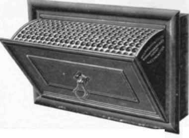
Fig. 569 - Air Inlet with Perforated Inlet plate.
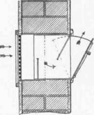
Fig 570. - Sheringham Air-lnlet. with Baffle - plates.
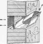
Fig. 571. - Sheringham Air Inlet, with Raffle -plates and Inner Wind-guard.

Fig. 572 - Sheringham Alr- Inlet Wood Bracket.
Fig. 577 shows a small appliance for fixing over a slit in the bottom rail of a window, and capable of being closed; it may be employed when windows cannot be opened, but can only admit a limited amount of air as a supplement to other openings. Hit-and-miss gratings for fixing in the meeting-rails of a sash-window can also be obtained. A deep bottom rail and bead to an ordinary double-hung sash permit of the window being opened to allow air to enter at the meeting rails.
These illustrations have been selected to indicate the many types of air-inlets now in the market. It will be observed that the object generally aimed at is the admission of air, so as to cause diffusion throughout the apartment, and to avoid a direct current or draught; but, as previously stated, they
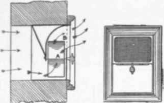
Fig. 573 - Air-Inlet with Regulating Valve A and brass gauze front B.

Fig. 574. - Air Inlet with Baffle-plate b, valve c and water-drawer e, are frequently employed too small in size, and improperly located, so that, when the suctional force within is powerful, they either fail in those particulars for which they have been designed, or else do not give an efficient supply of air, the result being draughts, or air drawn from other sources.

Fig. 575 - Drawer Air - Inlet, with Baffle-plates.

Fig. 576. -Air-Inlet with Movable Lourres.

IV 477- Air-Inlet fur Fixing on Bottom Rail of Window.
Rotary air-propellers or fans are now acknowledged to be the most economical appliances for impelling air into buildings when the plenum system is adopted. Various manufacturers have introduced different forms, the differences being principally in the form manufacturers and number of the blades. Fig. 578 shows one with two blades, and Fig. 579 shows one with six blades of a different shape. As, however, the plenum system, for which they are principally required, will not be fully discussed for reasons previously given, it is unnecessary to consider closely the several points of difference they present, or to go further into par-ticulars respecting their application.
The use of a spray of water for inducing a entrant of air in an extract-tube will be considered and illustrated in the next chapter; exactly the same arange-ments can be adopted for inlets.
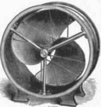
Fig. 578. - Howorth's Two-bladed Air-propeller or Fan.
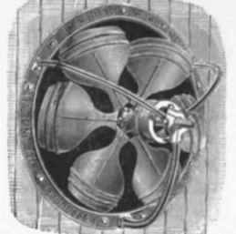
Fig. 579.-Baird, Thompson, & Co.'s Six bladed Air propeller or Fan.
Air-inlet cowls, such as those shown in figs. 580 and 581, are sometimes used; they are useful for spaces surrounded (or nearly so) by other rooms, such as halls

Fig. 580. - Elevation and Section of Donald & Sime's Air Inlet Cowl.
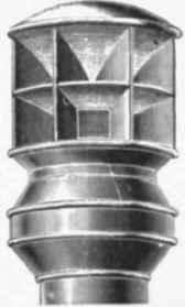
Fig . 581 -View of Baird. Thompson. & Co's Air Inlet Cowl and staircases, as well as in ordinary circumstances. They must be fixed on roots where the wind will have free play upon them, as they will otherwise let as outlets. In still weather also they will cease to serve the purpose for which they are intended.
Warmed-air inlets will be considered in Chapter VIII (Floors)., under the head of "Warning and Ventilation ".
Continue to:
My Books

