Table Of Strains Of Roof
Description
This section is from the book "Safe Building", by Louis De Coppet Berg. Also available from Amazon: Code Check: An Illustrated Guide to Building a Safe House.
Table Of Strains Of Roof
Name of piece. | Standing load. | Wind load. | Result. |
B.J. | + 76000 | + 8000 | + 84500 |
G. K. | + 61000 | + 8500 | + 69500 |
D. L. | + 46000 | + 8500 | + 54500 |
E. M. | + 46000 | + 15500 | + 61500 |
F.N. | + 61000 | + 15500 | + 76500 |
G. P. | +76000 | + 15500 | + 91500 |
J. K. | +12300 | + 11400 | + 23700 |
K. L. | +12300 | + 11400 | + 23700 |
L. M. | - 52000 | - 15000 | - 67000 |
M. N. | + 12300 | + 12300 | |
N. P. | - 12300 | + 12300 | |
R. Q. | - 24000 | - 12000 | - 36000 |
G.N. | -23500 | + 2000 | - 21500 |
J. O. | - 49000 | - 11000 | - 60000 |
Q. O. | - 23500 | + 6000 | - 17500 |
P.O. | - 49000 | + 7500 | - 41500 |
Fig. 265.
Figures 266 and 267 we reach exactly the same results, by combining both vertical load and wind pressure in one diagram.
In designing the truss, we must remember that were the wind blowing from the right, the corresponding members of each half of the truss would exchange their respective strains, we must therefore design each such pair of (right and left) members to resist the larger strain. Figure 268 gives the drawing of truss and detail of joints. In desiging the truss we find that the heaviest strains exist when the wind blows with the exception of the horizontal central tie Q O which has its largest tension, when there is no wind; we select accordingly, the heaviest strains for each member and proceed to design the parts. For the tie-rods we require areas, as follows :
Vertical rod L M =67000/12000= 5,58 square inches or a diameter of say 2 5/8 inches.
Inclined rod K Q=36000/12000 = 3 square inches or a diameter of say
2 inches.
Lower inclined rod J O=60000/12000 = 5 square inches or a diameter of say 2 1/2 inches.
Horizontal rod QO=23500/12000 =2 square inches or a diameter of say 1 5/8 inches.
By placing sleeve nuts (or turn buckles), as shown, we can tighten up the truss at any time.
We next design the struts to stand 23700 pounds compression each. They are 13 feet 4 inches long or 160 inches long. After several trials we decide to use two 3 inches x 3 inches x 1/2 inch tees, placed one inch apart, back to back. The weakest way in compression will evidently be with the neutral axis parallel to the web. From Table XXIV, we find their square of radius of gyration for this axis to be q2 = 0,42 and their area of cross-section = 2,75 square inches each or 5 1/2 square inches for the two.1
Detailing the truss-
Take heaviest strains.
Size of rods.
Size of struts.
1 It should be noted that no matter how many tees were placed along the same axis in the same directum we should have the same o2: for while each additional one would increase the area, and the moment of inertia i, and the moment of resitance r, the square of the radius of gyration o2, being simply the quotient of the inertia divided by the area, would remain constant, no matter how many tees were used.
We have then for the safe compressive stress in these tees to resist the 23 700 pounds compression, (see Formula 3) :
w = 12000.5 1/2/1+0,00005.1602/0,42 = 23322 pounds.
which is near enough. It should be noted that we consider the strut as a column with pin ends. The ends have got separately forged pieces, bearing on the pins and riveted between the ends of struts with eight 5/8 inch rivets.

The rivets were determined, as follows :
Bearing area of each rivet 5/8 inch x l inch = 5/8 square inch or =5/8.12000= 7500 pounds, value per rivet.
Shearing area of each rivet= 0,3068 square inches, there being two shearing areas to each rivet, we have 0,6136 square inches resisting shearing, or shearing value of each rivet = 0,6136.8000 = 4908 pounds.
For safe bending-moment on each rivet, we have from Table I, section No. 7 and from Formula(18) transposed : m =11/14. (5/16)3.15000 = 1/42.15000 = 360 pounds-inch.
Remembering to use the larger value (k/f) = 15000 pounds for bending-moment on pins or rivets, we could have read the same results for bearing, shearing and bending moment directly from
Rivets in strut ends.
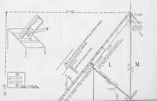
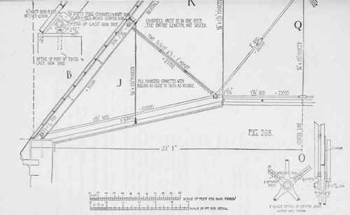
Fig. 268.
Tables XXXV and XXXVIII.
The actual bending-moment on all the rivets would be Formula
(21): m = 23700.1/8 = 2962 pounds-inch
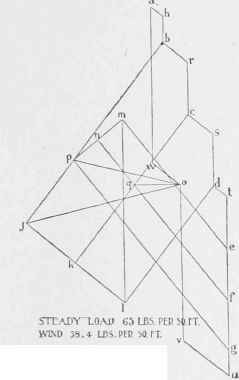
Fig. 267.
We require therefore, to resist bending
2962/360= 8,2 or say eight rivets.
This being more than required for either bearing or shearing determines the number of rivets to be used.
We next decide on size of pin used. It is evident that the joints will be similar as regards arrangement.
The largest rod will be central on pin, each side of it will be another rod and outside of this the strut. We can also readily see that the joint at foot of vertical rod L M will be the most severely taxed, and as it is usual to use the same size pin throughout a truss we will calculate for this joint. It is, also, evident that we need calculate only for the strains in the vertical line, as these will be the heaviest.
In order to reduce the bending-moment on the pin, we reduce the head or eye-part of vertical rod to 2 inches thick, this will make a compression of 67000/2 = 33500pounds per inch thickness and require a diameter of pin=33500/12000= 2,8 or say 2 15/16 inches diameter, (which was the nearest regular size of pin made by the mill who had the contract).
The same result could have Keen read directly from Table
Calculating the pins.
XXXVI. For the rod K Q we require a width of bearing
= 36000/2 15/16.12000= 1 inch.
For each strut we require a width of bearing
= 23700/2 15/16.12000 = 0,67 or say 3/4 inch. The single shearing area of pin being about 6 3/4 square inches or = 61.8000 = 54000 pounds, there can evidently be no danger from that quarter.
We now calculate the bending-moment, we first obtain the vertical resultants of all the strains, by laying off each strain along its respective line of action at a certain scale, and then measuring the length of its projection along the vertical line. The vertical projection of the 36000 pounds-tension is 28000 pounds pulling downwards; the projection of the 21500 pounds-tension is 16500 pounds pulling downwards; the projection of the 23700 pounds-compression is 15000 pounds pushing downwards ; the projection of the 12300 pounds-compression is 7500 pounds-compression pushing downwards; the sum of all of these is 28000 + 16500 + 15000+7500=67000 pounds downward. Resisting this we have the 67000 pounds of upward pull.
Continue to:
My Books

