The Tree House
Description
This section is from the book "The Scientific American Boy", by A. Russell Bond. Also available from Amazon: The Scientific American Boy.
The Tree House
The tree had two large limbs which extended out at a wide angle from the main trunk. Across these two limbs, at about seven feet out, we laid our first girder, nailing it securely in place. Then to the main trunk we nailed the second girder on a level with the first. Diagonal braces were extended from the trunk to support the ends of this girder, and a tie piece was nailed to the braces, as shown in Fig. 138, to prevent them from spreading. The girders were rough sticks about 4 inches in diameter and 10 feet long. We cut flat faces on them at the points where they were nailed to the tree, and then, to make them doubly secured, we nailed cleats, or blocks of wood, to the tree under them. The floor beams were then laid across and nailed to the girders. They were cut to a

Fig. 138. Main Girder of the Tree House.
length of 10 feet so as to project beyond the outer girder to provide for a piazza overhanging the Goblins' Platform. Six floor beams were used, spaced 20 inches apart. All branches projecting up between the beams were then cut away and a flooring of slabs was laid on. To the main
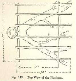
Fig. 139. Top View of the Platform.
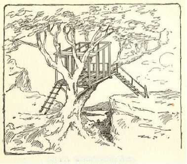
Fig. 140. The Frame of the House.
trunk six feet above the flooring, a stick or (to use the technical term), "wall plate," was nailed on, and its ends were supported by upright posts resting on the platform. Thirty inches from the outer end of the platform two more posts were erected eight feet high and secured by sticks nailed across from the other posts, and also by a second wall plate connecting their upper ends. Four more posts were erected, one between each pair of the corner posts, and then we were ready to enclose the framing.
The sidewalls were first clapboarded, because we were afraid the roof would not hold us until the framing had been strengthened by nailing on the siding. Slab boards were used for this purpose. Beginning at the bottom, the boards were laid on, each lapping over the one below, as shown in Fig. 141, so as to shed water. In each side we cut a window opening and nailed on a window casing of the type shown in Fig. 142, which will be described in a moment. As soon as the clapboards were applied, we nailed on the rafters and then applied the roofing. The same principle was here used for shedding water. The lowest board was first laid on, and then the others were successively applied, each lapping over the one below.
The window casings we used each consisted of a frame about 15 inches square, but with the upper and lower pieces extending 12 inches beyond one of the side pieces. On these extended pieces a slideway was formed for the window sash by nailing on two strips of wood about 3/4 inch square and over them a pair of wider strips projecting inward, so as to overlap the edges of the sash. The window sash consisted of a frame 13-1/2 inches square, made of 3/4-inch square strips over which canvas was tightly stretched and tacked. A spool was nailed on at one side for a handle. These windows were closed only in rainy weather, to keep the water out.
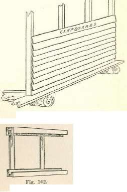
Fig. 141. Nailing on the Clapboards.
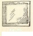
Fig. 142. The Window Casing.
Fig. 143. The Window Sash.
Continue to:
My Books

