Chapter VII. Push Buttons, Switches, Annunciators, Bells And Like Apparatus
Description
This section is from the book "Electricity For Boys. The "How-To-Do-It" Books", by J. S. Zerbe. Also available from Amazon: Electricity for Boys.
Chapter VII. Push Buttons, Switches, Annunciators, Bells And Like Apparatus
Simple Switches
We have now gone over the simpler or elementary outlines of electrical phenomena, and we may commence to do some of the practical work in the art. We need certain apparatus to make connections, which will be constructed first.
A Two-Pole Switch
A simple two-pole switch for a single line is made as follows:
A base block (A, Fig. 43) 3 inches long, 2 inches wide and ¾ inch thick, has on it, at one end, a binding screw (B), which holds a pair of fingers (C) of brass or copper, these fingers being bent upwardly and so arranged as to serve as fingers to hold a switch bar (D) between them. This bar is also of copper or brass and is pivoted to the fingers. Near the other end of the base is a similar binding screw (E) and fingers (F) to receive the blade of the switch bar. The bar has a handle (G) of wood. The wires are attached to the respective binding screws (B, E).
Double-Pole Switch
A double-pole switch or a switch for a double line is shown in Fig. 44. This is made similar in all respects to the one shown in Fig. 43, excepting that there are two switch blades (A, A) connected by a cross bar (B) of insulating material, and this bar carries the handle (C).
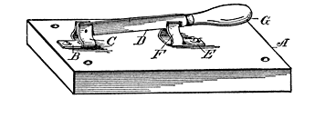 Fig. 43. Two-Pole Switch
 Fig. 44. Double-Pole Switch
Other types of switch will be found very useful. In Fig. 45 is a simple sliding switch in which the base block has, at one end, a pair of copper plates (A, B), each held at one end to the base by a binding screw (C), and having a bearing or contact surface (D) at its other end. At the other end of the base is a copper plate (E) held by a binding screw (F), to the inner end of which plate is hinged a swinging switch blade (G), the free end of which is adapted to engage with the plates (A, B).
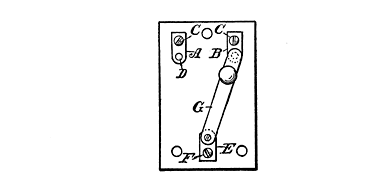 Fig. 45. Sliding Switch
Sliding Switch
This sliding switch form may have the contact plates (A, B and C, Fig. 46) circularly arranged and any number may be located on the base, so they may be engaged by a single switching lever (H). It is the form usually adopted for rheostats.
Reversing Switch
A reversing switch is shown in Fig. 47. The base has two plates (A, B) at one end, to which the parallel switch bars (C, D) are hinged. The other end of the base has three contact plates (E, F, G) to engage the swinging switch bars, these latter being at such distance apart that they will engage with the middle and one of the outer plates. The inlet wires, positive and negative, are attached to the plates (A, B, respectively), and one of the outlet wires (H) is attached to the middle contact plate (F), while the other wire is connected up with both of the outside plates. When the switch bars (C, D) are thrown to the left so as to be in contact with E, F, the outside plate (E) and the middle plate (F) will be positive and negative, respectively; but when the switch is thrown to the right, as shown in the figure, plate F becomes positive and plate E negative, as shown.
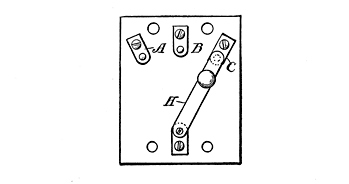 Fig. 46. Rheostat Form of Switch
Continue to:
My Books

