How To Make A Hand Camera
Description
This section is from the book "Cassell's Cyclopaedia Of Mechanics", by Paul N. Hasluck. Also available from Amazon: Cassell's Cyclopaedia Of Mechanics.
How To Make A Hand Camera
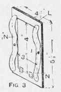
In constructing a hand camera, first fix up a suitable lens of about 5 1/2in. focus in a box, ascertain exactly the principal focus, and see, also, whether the lens covers a 3-plate satisfactorily; that is to say, with a stop having a diameter equal to one-eighth the locus (or about 11/16in.) the lens should give a sharp image right to the extreme corners of the plate. The principal locus, plus the distance from the stop B (Fig. 1) to the edge of the hood C, and the width of the slide D, 1/4in. for springs, together with an allowance of 1 in. focal adjustment, should constitute the inside length of the camera. Having constructed the framework, fix the lens board p at the required distance, which is found by focussing a very distant object on a piece of ground glass placed exactly 3/4in. from the back. Next lit a frame at H, and remove a portion of the top of tile framework at M (see Fig. 2) to allow of the insertion of the slide. Construct the frame L (Fig.3) with springs N to force the frame into accurate register and tit the door I, through which the image may be focussed on a celluloid focussing screen. This screen consists of a light frame to carry a sheet of celluloid, the screen sinking into a rebate gauged to match that of the slide. The front door is next fitted, and carries two Anders, a pattern for which appears in Fig. i. The lenses are let into the front by sinking a hole of the diameter of the lens to within one-sixteenth of its total thickness, and then cutting a smaller hole. After dropping the lens into its recess the lens may be held against the shoulder so formed by springing in a rim of wire. The edges O, 0 are bent over, and a bend is also made along the dotted lines. The frame formed by the bent pieces carries a strip of looking-glass on the parts P, and is screwed to the front door, so that the hole covers the lens. The focus of these finder lenses should, proportionately to the screen, be slightly less than that of the chief lens, so that the image in the finder can be blocked out until it coincides with that on the screen.
A piece of ground glass is fixed beneath 0, 0. The frame H (Fig. 1) should be covered with velvet, so that when the slide is inserted through M (Fig. 2) the springs force it against II and make a light-tight join. Dark slides may be bought cheaply, or may be made as follows. Groove some pieces like Fig. 5 (two 5 in. and two 4in.) and dovetail into a frame, with a piece of blackened zinc fitted into a groove R to make the light-tight division. Before fitting. however, cut away the parts J from the top rail on each side, until these parts are flush with the underside of the groove. Glue a strip of velvet between the points K and K (see Fig. 6), and shape the rails S. Glue a narrow strip of black paper across just below Y to act as a light trap, and fasten a spring like it at V and U (Fig. 5). The plate rests on these springs, and is forced upwards against the top rail. When a piece of vulcanite or vulcanised fibre has been cut and fitted as the draw shutter, the ivory number inserted, and the draw strap attached at W (Fig 6), the slide is complete. The camera may be covered with Roanoid or imitation morocco. The lens must be fitted with rack and pinion, the latter to be brought out through the side of the camera, and fitted with a pointer, against which a scale of distances may be fixed. A covered nut may be let into the side and one into tile bottom of the camera, so that a stand may be used when required. A time and instantaneous shutter is shown at X (Fig. 1); the principle of such a shutter is explained on p. 187. The dark slide i as made above are so light that several of them, each holding two plates, may be carried in the pockets.

Fig. I.
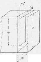
Fig. 2.
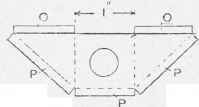
Fig. 4.


Making a Hand Camera.
Continue to:
My Books

