Pattern For The Soffit Of A Semicircular Arch In A Circular Wall, The Soffit Being Level At The Top And The Jambs Of The Opening Being At Right Angles To The Walls In Plan. Two Cases. Continued
Description
This section is from the book "The New Metal Worker Pattern Book", by George Watson Kittredge. Also available from Amazon: The new metal worker pattern book.
Pattern For The Soffit Of A Semicircular Arch In A Circular Wall, The Soffit Being Level At The Top And The Jambs Of The Opening Being At Right Angles To The Walls In Plan. Two Cases. Continued

Fig. 726. - Plan and Elevation of Arch in a Circular Wall - Second Case.
If the arch were semi-elliptical instead of semicircular, the method of procedure would be the same as above described.
Second Case. - In Fig. 726, ABC represents the outer curve of an arch in circular wall, as shown by A'HC' in plan. EBD represents the inner curve in elevation, as does E' D' the same in plan. Then AEBDC represents the soffit of the arch in elevation mid A' H C' D' E' the same in plan. The conditions given in this case differ from those of the first case only in the fact that the inner curve of the arch in this case is straight in plan, as shown by E' D', instead of curved to the radius of the wall as in Pig. 722. The method of procedure in this case is exactly the same as before, but one less operation will be necessary, since measurements upon the inner curve may be taken directly from E B D of the elevation.
To avoid a confusion of lines, a duplicate Solid Lines of Plan, Fig. 726. of E B D of elevation has been drawn in plan, as shown by E' B' D'. To obtain the divisions on plan divide AB into any convenient number of equal parts. and from the points thus obtained drop lines parallel with the center line B B' to A' H of plan, as shown. Divide E' B' in a similar manner, and from the points thus obtained drop lines to E' F' of the plan, as shown. Connect points in A' H' with those of similar number in E' F' by solid lines. Also connect points in A' II with those of next lower number in E'F'by dotted lines. These solid and dotted lines just drawn will form the bases of a series of sections, shown in Figs. 727 and 728, whose upper lines will give correct distances across the pattern of the soffit.
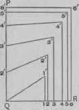
Fig. 727. - Diagram of Sections on

Fig. 728. - Diagram of Sections on
Dotted Lines of Plan, Fig. 726.
To construct the sections based upon the solid lines of the plan, first draw the right angle P Q R in Fig. 727, and set off on Q P. measuring from Q, the length of the vertical lines in A B F of elevation. Starting from Q, set off on Q R the length of solid lines in A' H F' E' of plan, as shown by the small figures in Q R. With the T-square parallel with P Q, draw lilies from the points in Q R and, measuring from Q R, set off on these lines the length of lines of corresponding number in E' F' B' of plan, and connect the points with points of similar number in P Q. The diagram of sections based upon the dotted lines of the plan, shown in Fig. 728, is constructed in the same manner, using the length of dotted lines in plan for the distances in N 0, the length of lines in E' F' B' of plan for the length of lines set off at right angles to N O, and the; length of lines in A B F of elevation for the distances in M N. Connect the points as indicated by the dotted lines of the plan, all as shown.
The next step is to obtain the correct distances between points in A B of elevation, or A' H of plan. To do this lay off horizontally J K, on which set off a stretchout of A' H of plan, and, with the T-square at right angles with J K, draw the usual measuring lines. with the T-square parallel with J K, carry lines from the points in A B to lines of similar number. A line can be traced through these points, as shown by J L, from which the correct stretchout of the outer side of the pattern can be obtained.
To describe the pattern first draw any line, as a e of Fig. 729, equal to A' E' of plan. With e of pattern as center, and E' 1 of the inner curve of the arch as radius, strike a small arc, 1', which intersect with one struck from a of pattern as center, and Q 1' of Fig. 727 as radius, thus establishing the point 1' of pattern. With a of pattern as center, and J 2 of Fig.
726 as radius, describe a small arc, 2, which intersect with one struck from 1' of pattern as center, and 1' 2' of Fig. 728 as radius, thus establishing point 2 of pattern. Then from 2 as center, with 2' 2' of Fig.
727 as radius, strike a small arc, 2', which is intersected with one struck from 1' of pattern as center, and 1 2 of the inner curve of the arch as radius, thus definitely establishing the point 2' of pattern. Continue in this way, using the tops of sections in Figs. 727 and 728 for measurements across the pattern, and the spaces in the inner curve E' B' and in outer curve as developed in J L. Fig. 726, for the distances about the edges of the pattern, establishing the several points, as shown. Connect points h and f with a straight line, and through the intermediate points trace the curves, as shown. The other half of pattern can be obtained by the same method or by duplication.
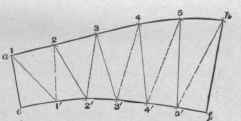
Fig. 729. - Half Pattern of Soffit Shown in Fig. 726.
Continue to:
My Books

