A Model Steam Turbine
Description
This section is from the book "Amateur Work Magazine Vol3". Also available from Amazon: Amateur Work.
A Model Steam Turbine
W. Halcot Hingston
The steam turbine, where used as the propelling machinery of a model steamer, has several distinct advantages over engines of the reciprocating type. When designing machinery for model steamers the chief difficulties are; - The small size of the engine room, the difficulty of making sufficiently powerful machinery light enough for the displacement, and the further difficulty of keeping the centre of gravity of the said machinery sufficiently low down to make the boat seaworthy. The steam turbine gets over all these difficulties, it being small, light for its power, and it can be put at the very bottom of the boat.
There are two types of steam turbine which have proved specially successful in actual practice (i. e., not model work) these being ; - The De Laval (jet type), the Parsons (parallel flow,) In building a model, one or the other of these types may be used, but in a modified form ; and as the Parsons turbine would make a very difficult and complicated model, a modified type of the De Laval turbine has therefore been chosen by the writer. Of course, a steam turbine can be used for many other purposes, but its advantages are more marked in model steamer work, and, therefore, I shall endeavor to explain how one can be constructed suitable for a boat about 5 ft. long, which seems to be the most favored size amongst model makers.

Fig. 2.
The De Laval turbine is an impact turbine, and consists essentially of a wheel carrying a number of suitably shaped vanes, on which steam impinges from one or more nozzles. As nothing definite is known about the power which a model turbine of any particular size will develop, the governing factor must be the amount of steam with which it can be supplied. A model steamer of about 5 ft. in length can easily be fitted with a boiler having from 100 to 150 sq. in. of heating surface. Assuming, therefore, that we have a boiler with 120 sq. in. heating surface, working at 30 lbs. per sq. in, about 1.2 cubic in. of water will be evaporated per minute, which will give 686.4 cubic in. of steam at 30 lbs. pressure.

Details Of Model Steam Turbine
(DE Laval Type.)
By W. Halcot Hingston.
The total jet area which the boiler will supply can approximately be found from Rankine's formula: w = weight in lbs. of steam at absolute pressure a = area in square inches of jet b = absolute pressure of steam
But the co-efficient of discharge is .9, and therefore, the area required should be .0012. This gives a jet diameter of .04 in. The steam nozzle is made from a piece of brass rod, outside diameter 7/32 inch. (bare). A hole .04 in. diameter is bored through the middle of it, and is tapered out as in sketch. The method of attachment of the nozzle is described later on.
The vane wheel of the turbine consists of a boss, round which a number of suitably shaped vanes are fixed. Outside these vanes is a brass band to keep the steam from escaping through centrifugal force. The dimensions and appearance of the wheel can be seen in Figs. 4 and 5. The boss (Fig. 7) is made of either brass or gun-metal, and can be built up or turned from a casting, the latter course being preferable. Its dimensions are: - Diameter of side plates, 1 1/2", diameter of centre, 3/8", thickness of plates, 3/32", distance apart of plates, 5/16".
The centre of the boss extends on one side of the wheel, so that it can be fixed to the shaft by a pin driven right through. In the edges of the plates twenty-four equi-distant cuts are made with a fretsaw, into which the bottom edges of the vanes are sweated. These cuts are at an angle of about 40 degrees, with the side of the plate. The correct shape for the vanes has next to be determined.
Referring to Fig. 6, A C represents the velocity of the steam (about 888 ft. per second) in magnitude and direction, the jet being at 20 degrees to the side of the wheels, and A D equals the linear speed of the wheel, where the jet impinges upon it (about one-third velocity of the steam). Completing the parallelogram, A B equals motion of the steam relative to the wheel. If the vane is then made so that A B is tangent to it at one edge, the steam will glide on without shock, and can then be deflected by the vane. Draw from A, A E at right angles to A B, then Q, the point where A E cuts the centre line of the wheel, is the centre from which, with radius Q A, the section of the vane is drawn. This radius equals 9/32". The vanes are made from No. 28 B. W. G. brass, 3/4" long, and having the curve just found.
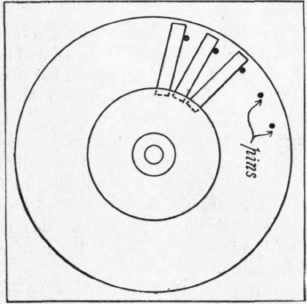
Fig. 9. Fixing Blades.
A simple device for making all the vanes identically the same can be made as follows : - Clamp two pieces of iron together (Fig. 8), and drill a 5/8" hole through them, whose centre is 1/8" from the joint, then on separating them, we shall have a mould slightly bigger than the vane. A piece of rod must now be turned up 9/16" in diameter, this must be filed away until it is just flush with the top of the mould, when a piece of 28 B. W. G. brass is between them. Twenty-four pieces of brass are then cut 3/4" x 11/16", these must be carefully annealed and cleansed, they are then placed on the mould, and forced in by hammering the core on top of them. A few strokes with a file will remove the edges of the brass which protrude.
The boss, mounted on a mandrel, is now firmly fixed to a piece of wood with a hole 3 1/4" in diameter by 5/8" deep, turned in it. A circle of ordinary pins must now be driven into the bottom of the hole at equal distances apart. The diameter of this circle should be about 2 3/4" (Fig. 9). The vanes are now pushed into the saw cuts in the boss, the backs of their outer ends being against the pins. In this way the vanes are held in their places radially.
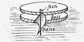
Fig. 9a. Sketch of Fixing Blades.
When all the vanes are in position, a thin mixture of plaster of Paris must be poured into the hole in the wood. When the plaster has thoroughly set, the boss and vanes, firmly imbedded in the plaster, can be taken from the board, the pins having been previously removed. It must then be mounted between centres, and carefully turned down to 2 7/8" diameter. The outside ring for the wheel is made from a piece of solid drawn brass tubing, 3" diameter and 11/16" wide, this must be thoroughly annealed, and one edge spun over, as in Fig. 4 and 5.
The plaster of Paris must now be carefully chipped away for a depth of about 1/4" from the ends of the vanes, and the brass ring slipped into place. A thin layer of solder is then sweated into the inside of this ring, which fixes the outer ends of the vanes firmly to it. The plaster is then chipped away from the other ends of the vanes, which are then sweated to the boss. The other edge of the brass ring must now be carefully spun over. When the remaining plaster of Paris is removed the wheel will be found to be perfectly true and strong.
The shaft is turned from a piece of steel 7/16" diameter, and has a disc left at one end in which teeth are cut for the necessary gearing. Its dimensions are:- length, 2"; diameter, 3/16"; diameter of boss, 3/8"; width of boss, 1/4". The ends of the shaft are pointed and hardened and run in two hollow centres. The boss of the wheel is bored a good fit on the shaft and is secured by a small pin driven right through it. The case of the turbine consists of two castings, Figs. 10 and 11, fitting into the ends of a piece of 3 1/2" diameter, solid drawn brass or copper tube, the whole being held together by five bolts, as shown. These castings can be made in either brass or aluminum, preferably the latter.
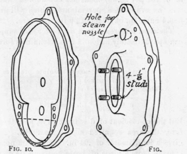
Ends of Turbine Casing.
Referring to Fig. 1, it will be seen that the left hand bearing for the shaft consists of a steel plate with a counter-sunk boss in the middle, which is attached to the end casting by four 1/8" studs, shown in Fig. 11. The boss must be deeply case-hardened for the end of the shaft to run in. The space between the steel plate and the end plate forms an oil chamber, the oil being conveyed to the bearing by a ring as in dynamos.
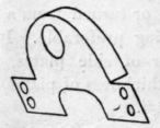
Fig. 13. Oil Bath Casing.
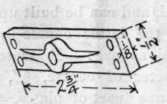
Fig. 12. Bearing for Counter.
The right hand bearing is a 1/4" countersunk steel stud, screwed through a boss in the end plate, and held in position by a lock nut. This stud is also hardened. The pinion on the shaft gears into a gunmetal wheel 1 13/32" diameter, mounted on a 3/16" shaft. This is supported on the left by a gunmetal bearing (Fig. 12 ), screwed to bosses on the end plate.
A thin brass plate is soldered on the inside of the right hand end plate, as shown by dotted lines Fig. 10. This forms an oil bath in which the gear wheel runs, thus carrying oil to the pinion and bearing, and a thin brass cover should be put as in Fig. 13, to keep the oil from splashing all over the case. Oil cups and drain cocks can be fitted as shown to both oil baths. A small hole B, Fig. 1 is bored in the end plate to allow any condensed steam to drain from the case, and also in the end plate of the turbine case, and is reamed and filed until the steam nozzle fits in it at an angle of 20 degrees to the plate. The nozzle is held in place by a brass bracket sweated to it, which is fastened by two screws to the end plate. The joint between the nozzle and the end plate should be sweated with soft solder to make it steam tight. The exhaust steam passes through a 1/2" diameter tube soldered into the side of the casing.
Before putting the machine together, the vane-wheel should be run between centres and balanced as well as possible by scraping away pieces of solder from the rim of the wheel. When finally adjusting, the vane-wheel bearings should be left the least bit slack, so that the wheel may rotate about its centre of gravity. This is provided for in real De Laval turbines by having a long, flexible shaft, which, however, is impracticable in a model. The above slackness will not effect the gearing, as the steam will force the shaft against the right hand bearing, so that the pinion will remain practically central, any slight eccentricity occuring at the left hand bearing.
Continue to:
My Books

