Acetylene Generator For Magic Lanterns
Description
This section is from the book "Amateur Work Magazine Vol3". Also available from Amazon: Amateur Work.
Acetylene Generator For Magic Lanterns
The acetylene generator here described is of ample capacity for providing sufficient gas for an evenings use of the magic lantern described in the previous number of this magazine. It is perfectly safe to operate, if the ordinary precautions attending the use of any illuminating gas are observed. Granulated carbide is used of about 1/4" screen. The pressure is easily regulated by weighting the bell B with rings of bar iron large enough to slip down over the carbide chamber G.
The tank A is made of fairly heavy galvanized or tinned iron, and is 18" high and 15" diameter. To the outer sides are soldered two pieces of 1/4" round iron rod g 12" long, which serve as guides for the bell B. A piece of 1/4" iron pipe D), 22" long is bent 16" from one end, put through a hole punched in one side of the tank, and carefully soldered rigidly in position, where it passes through the tank and by means of a brace d, bent as shown and soldered to the bottom.
The main part of the gas bell B is also made of galvanized iron and is 15" high and 12" diameter. The top is a disk with a centre hole, 4" diameter, cut through, and to the edges of which is soldered the tube F. The guides D of iron are also soldered to the top of bell, and are 5" long, and 1" wide ; holes §" diameter being punched 1" from the ends for the rods g. Across the bottom a guide f for the plunger rod is fitted. It is made of hoop iron, 14" long, and 1" wide, 1" at each end being turned up and riveted to the sides of the bell. The 5/16" hole should be in the exact centre. The guides k are fitted to the lower, outer edge of the bell, serving to keep it centered in the tank. The guides should be about 1/8" scant of meeting the sides of the tank. They are made of strips of hoop iron 6" long and 1 wide bent to the shape shown and riveted to the bell, the lower end being riveted first and before bending.
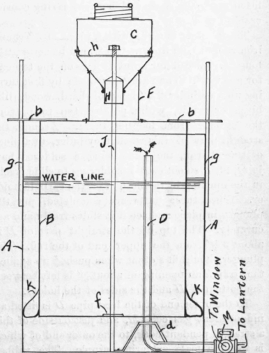
The tube F is also made of galvanized iron and is 4" diameter and 4" high, the joints with both the bell and carbide chamber, C being strongly made and well soldered. The carbide chamber G likewise made of galvanized or tinned iron is much after the shape of an inverted oyster or milk can, only of larger size, and with a 3" opening in the top fitted with a screw cover, similar to those used on preserve tins, which must be gas tight. This will undoubtedly have to be made up at a tin shop, but will not be expensive.
The bottom slopes inward at an angle of 50°, the hole in the centre making a close sliding fit to the plunger H, which is 1 1/2iameter. A strap h, 8" long and 1" wide, with the ends turned up 1", is fitted across the chamber as shown, a 5/16le in the exact centre acting as a guide for the plunger rod J. If possible, have the edge of the hole at H urned around a wire bail to give strength and stiffness. Certain forms of coffee tins fitted with screw tops, are obtainable in large cities, which could be cut down and fitted with the V shaped bottom, saving considerable work.
The plunger is made with a piece of 1/4round iron rod, or cold drawn steel would be better, 24" long. A thread for a nut is cut on the top end for about 2". The part IT, is made by first turning up a cylinder 2 1/2" long of hard wood, like birch or maple, with a pointed top to prevent the carbide from lodging there. Around the straight part of this wooden cylinder, fit a piece of tinned iron, the joint being a soldered butt joint, filed smooth after soldering to slide freely in the opening in the bottom of the carbide holder. When these parts are completed, put the plunger in place and see if it slides freely and accurately. The top of the straight part of H is about 2 2 1/2" from the upper end of the rod. The plunger should fit so that when pushed up against the strap h an opening of about 3/8" is left between the bottom of H and the sides of the holder.
To the outer end of the feed pipe D is fitted an independent gas cock M, and just outside of this a straight pendant cock, to the outer end of which is fitted a male soldering nipple. The rubber gas tubing to the lantern is fitted over this nipple. Another piece of tubing is run to an adjacent window from the end of the independent cock, this being used to let off any excess of gas which might be generated by the dropping of considerable carbide. Should the plunger show any tendency to stick during operation and not close readily, bore holes in the wooden cylinder and run in moulten lead; the additional weight will prevent this, or the part H can be made of a solid piece of cold rolled steel shafting, a hole being drilled through the centre for the rod J.
The operation of the generator is as follows : -The tank is filled with water to a depth of about 12", the bell placed in position, and held from dropping to the bottom of the tank by placing pieces of wood under the guides D and resting on the top of the tank. The cover of the carbide holder is removed, the required quantity of granulated carbide, 1/4" screen, placed in the holder; the cover immediately replaced and screwed firmly down ; the sticks removed from under the guides thus allowing the bell to sink; the rod J resting on the bottom of the tank, causes the plunger H to open as the bell settles and a small quantity of carbide drops into the water; gas generates causing the bell to rise so that the plunger closes the opening in the bottom of the carbide holder, and the feed of carbide ceases until enough gas has been consumed to cause the bell to again drop low enough to again open the feed hole. When generation first begins, open the cock Mto allow the air in the holder to escape, closing it when acetylene begins to flow. When through using, if the carbide is about used up, take into the open air and empty, using care that no lamp or other flame is near at hand. An electric hand-lamp is the best thing for such work.
Continue to:
My Books

