Telephone Circuits And Wiring. I. A Simple Arrangement For Short Lines
Description
This section is from the book "Amateur Work Magazine Vol3". Also available from Amazon: Amateur Work.
Telephone Circuits And Wiring. I. A Simple Arrangement For Short Lines
Arthur H. Bell.
The subject of telephones and their application to private uses is a matter sparsely treated in electrical text books and technical publications. Much importance has been given, in such works as have been offered to the public, to detailed descriptions of the construction of various types of transmitters, receivers, and similar apparatus, fronTearliest days of experiment to modern times, and but little space has been devoted to the ar-ranging of systems of easy practical communication between two or more distant points, with such diagrams of circuits as will help the nontechnical reader to establish telephone service without the aid of a practical telephone electrician.
In this, and the following chapters, the ordinary transmitter or receiver will be treated purely as an article of commerce, for sale at reasonable prices and returnable as junk when rendered worthless by long service.
What interests the layman most, is not what distinctive electrical features one type of apparatus possesses over another, but by what method any good type, of which there are scores in the market, may be connected together for house to stable, room to room, or factory to office service. It is the purpose of this article to cover intelligently a number of circuits of value to readers in all parts of the country. Possibly many arrangements best adapted to one's specific needs may not be treated until later chaptirs, but it is advisable for the reader to follow all of the circuits as they are explained, thereby gaining a liberal understanding of wiring methods.
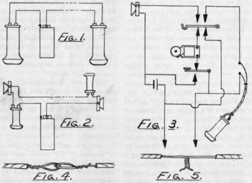
The most simple arrangement of the telephone is a circuit, Fig. 1, comprising two ordinary receivers and a cell of battery. Conversation by this method is limited to short distances and not worthy the trouble of connecting the apparatus except for experiment.
The next arrangement is the addition of a pair of transmitters to the circuit, as in Fig. 2. The same circuit, with battery at each end, will facilitate talking. This permits easy conversation for quite a distance, but no means of signaling. It will be noticed that these circuits are closed at all times and consequently would wear constantly upon the battery supply if a switch to open the circuit were not inserted to prevent exhaustion.
A simple method of setting up instruments for practical usage between two points is shown in Fig. 3, where the length of line construction is to be limited to the distance over which an ordinary electric door bell may be operated for signaling. This arrangement is splendidly adapted to room to room or house to stable circuits, where the line length is less than 1000 feet.
This diagram represents the equipment of one station complete, if we spread it out before us for inspection. The hook is, perhaps, the most important part, as everything depends on the proper make and break of the contacts when the receiver is taken off and replaced. The receiver must be kept on the hook when not in use.
Let us now discuss the circuit piece by piece. One side of the line takes one side of the battery. The other terminal of the transmitter goes to one of the upper hook contacts. These upper contacts do not touch the metal hook until the receiver is removed. The second upper contact takes a binding post (not shown in the diagram), and after we have connected our flexible receiver cord to the receiver, one of the two ends is connected to this binding post. The other side of the receiver cord goes to a binding post connected with the other side of the line. With the receiver off the hook we are enabled to talk with and hear the party at the other end, because the circuit between transmitter and receiver is established by the hook after it goes up. Now, in signalling it is desirable to utilize the same sets of batteries, and the ringing circuit must be so devised that the downward contact of a strap key will place the battery in circuit across the line, thus ringing the bell at the other station as long as the key is depressed. The key, when restored, makes a contact with a contact point connected with one side of the bell, and the other side of the bell takes a contact point on the other side of the hook. The second under hook contact goes to the side of the line, where we started. It will be readily seen, with the strap key making upward contact and the receiver hook bearing on lower contacts, how a ring from the other end of the line will operate the signal bell. The reader should trace out this circuit until it is fully understood. It is not advisable to operate this system with one side of line grounded; the circuit should be metallic, that is, consisting solely of wires from station to station, to get the best results.
Readers may purchase transmitters and receivers at electrical stores and arrange wiring and working parts inside of a small wooden box, being careful to solder all connections carefully.
It may be observed that no induction coils are used in connection with this set. (On systems designed for short distances the induction coil has no value.) Induction coils are wound and used to raise the transmitted voltage, so as to overcome line resistance. In a subsequent chapter a diagram utilizing an induction coil will be shown.
In placing wires between stations, within doors, a number of important rules of installation must be obeyed. Foremost among these is the rule to avoid at all times crossing of other wires and, in cases where it is absolutely necessary to pass over other circuits, to thoroughly protect your wires by extra thick layers of insulation, from any chance of cross due to direct contact, chafing, un-expected moisture, or breaking of wire or insulation of either circuit.
For interior construction, in residences where neatness and partial secretion of wires is essential, wire known as No. 16 or 18 paired annunciator or office wire may be used, but where wires are to be concealed from close inspection, as under floors or behind sheathing or plastering, strict observance of fire underwriters' rules and rules for wiring as established by municipal legislation is necessary. In cellars and damp places, or places likely to be damp at certain periods, the wire should be well protected by heavy, damp-proof insulation of rubber, or similar compound. In tacking wires to the walls, use as few tacks as possible and avoid setting one tack over two wires of a circuit.
In splicing two pieces of wire together, never make what has been styled a bell hanger's joint, Fig. 4, for such connections are not perfect conductors and would be an endless source of bother. Always scrape the copper wire clean and bright and twist the two ends firmly together and solder securely, Fig. 5; then insulate the splice with a layer of electrician's tape.
Continue to:
My Books

