


Current Reverser For Spark Coil
Description
This section is from the book "Amateur Work Magazine Vol3". Also available from Amazon: Amateur Work.
Current Reverser For Spark Coil
A spark coil is very incomplete without a commutator. One of a very simple kind, and much easier to make than the usual variety fixed to coils, is figured below. This is a modification of one illustrated in Mr. Hare's book on large induction coils, and on all fours with a reversing switch fitted by Carlisle & Finch, of Cincinnati, to their model motors and electric cars.
A is a piece of stout sheet brass, about 1" X 3"; in the centre of this a hole is made to exactly fit a piece of brass tubing B, (triplet tubing used by makers of fishing rods will do for this.) B is about an inch in length, and should be soldered to A and fixed upright. C is a piece of brass tubing 1/2" longer than B, through which it passes; it should make rather a tight fit in B. In one end of C fix, by soldering, a small brass bolt, the head of which should just go in the end of tube, and may there be fixed. At the other end of C, drill two holes exactly opposite each other, and large enough to take a piece of stout brass rod, J about 2", this also may be soldered.
D is a thick disc of ebonite. This is secured to the bottom end of C by, having drilled a hole, passing it over the brass screw and securing it with the nut. It follows that if the handle or T-piece be turned, the ebonite disc is revolved, anything mounted upon it being quite insulated. The T-piece should be fitted so that the ebonite disc is kept close to the plate A, and without shake. E E are two brass studs securely inserted at opposite sides in the under side of the ebonite disc. Securely soldered to each is one strand of the best silk and rubber covered twin flexible wire. The best way I think to do this is to get two pieces of the smallest gauge copper or brass tubing, 3/16", say. Drill a small hole near one end, and, having bared"a strand of the wire, pass it through the hole and out at the end. Then plug this end with a piece of brass rod, and make a perfect joint with solder. The two studs, or short tubes, being done in this way, may then be securely fixed to the disc, as shown. They are, of course, perfectly insulated one from the other by the rubber and silk covering.
The brass platform A, is mounted on two wood mahogany blocks, G- G, these again glued to a gas block. Two terminals are then attached, as shows, HH, and hard brass or German silver springs adjusted, H B, so as to make perfect contact with the studs E E, as shown in the plan, Fig. 2, where is shown the under side of the ebonite disc, the two studs, and the two springs pressing against them. Ebonite or wood handles are fitted to the T piece, and the protruding end of C covered with a little ebonite cap.
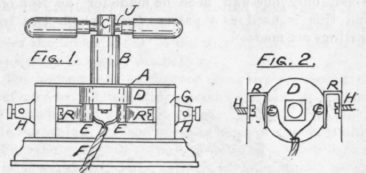
The twin wire is attached, one strand to the contact pillar, and the other one to one of the primary wires on the coil. The wires from the battery are then brought to the two terminals, H H. The handles being in a line with the base, as in the figure, a current passes, which current is reversed if the handles are turned the reversed way. With the handle set at right angles to the base the current, of course, is switched off.
Mr. Hare's remarks accompanying his design of switch may be quoted; - " In the ordinary commutator there are four joints where resistance may be found viz., at the two bearings of the cylinder, and at the two springs. These may be reduced to two, and the contact much improved."
Continue to:


My Books

