The Grindstone And Its Use
Description
This section is from the book "Amateur Work Magazine Vol3". Also available from Amazon: Amateur Work.
The Grindstone And Its Use
Olcott Haskell
Sloyd Instructor, Hitchcock Military Academy, San Rafael, California.
The dirt and inaccuracy usually accompanying work at the grindstone are certainly not attractive features, and it is the object of the writer to suggest ways in which these objections may be lessened and the work made more agreeable. Assuming that we have an ordinary foot-power grindstone some 18" in diameter x 2 1/2" thick, mounted after the customary manner in an open wooden frame, it should be clamped securely to the axle with the bearings true and in good order that all parts may run easily.

An important point to consider is the water supply, since !tis necessary during grinding to have the stone thoroughly wet to keep the tool from heating, and also to wash away the dust and waste particles of steel, thus keeping the surface of the stone in good cutting condition. If the lower portion of the stone is run through water (as is frequently done) it will pick up more water than is necessary, the excess splashing and dripping, also when the stone is left standing the part in contact with the water is softened, causing the stone to wear more on that side and become eccentric. Hence the most satisfactory arrangement is to have a small drip-can above the stone, and a trough or pan beneath to catch the waste water.
For a drip-can secure an open tin about 4" in diameter x 4" deep and near one edge drive a centre punch from the inside through the bottom. Melt a drop of solder to the jagged edges of this hole and work the punch through the hole until the edges are quite smooth and even. A piece of wood pointed to fit loosely in this hole makes an excellent drip faucet. Prepare a holder for this can by fitting a 3-4" dowel into a hole bored in the frame at the back of the grindstone, slitting the top of the dowel with a saw to receive the ends of a wide band of heavy tin, which band should be bent loosely around the can and nailed securely in the saw slit. A piece of wood 1-2" x 4" x 7" nailed to the front of the dowel prevents the can from falling through the holder, and also arrests drops from the stone. By revolving the can the water may be made to fall on whatever part of the stone it is most needed.
To catch the waste water secure a sheet of rather thin zinc 13" wide, x 36" long and bend up the sides to form a square trough 36" long, x 6" wide x 3 1-2" deep. Then at one third of the length from either end crimp and fold in the edges, so as to cause the end portions of the trough to stand up at an angle of about 60° with the base. This folding must be done carefully and edges of the folds should be left somewhat rounded, as. hammering the zinc flat might break it, causing leaks that would have to be stopped with solder or melted paraffin. Bore or punch a 1/2" hole in the centre of the trough, and by working around carefully from the inside with tapering instruments, such as the rounding handles of a small pair of pliers, burnish and spread the edges until the hole is about 3/4" in diameter. This action shonld form a smooth rounded lip to the hole so that it may be securely plugged with a rubber stopper. The grindstone must now be removed from its frame and the completed trough nailed in. Such a trough is easily made, and having no joints it cannot leak. In practice it will seldom need emptying, as the water usually evaporates between the periods of grinding. A shallow hopper-shaped frame may be secured around the sides of the stone to catch stray drops, and lead them where they shall fall into the zinc trough.

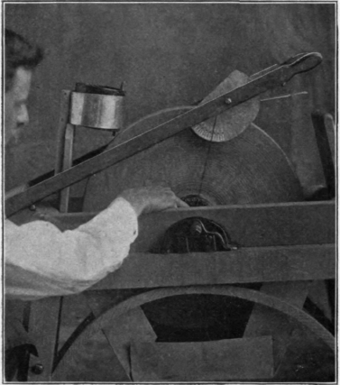
The grindstone will now be in a much rcore usable condition than at first, but still our best efforts at grinding will be merely guess work so far as accurate angles are concerned. The following grinding frame is designed to enable us to grind accurately to any desired angle. The accompanying photographs give excellent general views of this frame together with the other fittings, and Fig. 1 gives a top view of the npper end of the frame, while Fig. 2 shows a protractor for measuring the angles.
The grinding frame is formed of the two maple strips F F' 1-2" x 1 1-2" x 3/8" which have their lower ends secured to a block of oak or maple 1 1-2" x 6" x 13", and terminate in handles which are joined by having the inner tool frame A-E-E' pivoted between them on the screws S-Sr The entire frame is hinged to the rear of the grindstone support, and is weighted at its lower end, so that when not in use it swings into a vertical position. A firm T hinge should be used and it should be fastened by a single screw to the under side of the block on the grinding frame so that this frame may have motion from right to left as well as up and down.
Referring to Fig. 1, A, is a piece of maple 1" x 2 1/2" x 5 1/4" beveled off along its front edge so that the edge of the tool, which should extend 3-16" out beyond the block, may be readily seen. Tools are secured to the under side of this block by a strip of 5-16" x 1 \" x 5" maple clamped by the two 1-4" x 2 1-4" carriage bolts fitted with thumb nuts as shown. To one end of A is firmly screwed the protractor B, shown more clearly in Fig. 2, where the dotted lines indicate the position of the end of A when secured in place. This protractor may be made of heavy sheet brass or of galvanized iron and should have its outline formed by arcs of circles described from the centres C and D respectively as shown. C is a 1-4" hole drilled to receive the round headed screw S. D is a small hole just large enough to admit one end of a short length of flexible twine which is secured in the hole by a knot at the back. D is in line with the prolonged edge of the tool to be ground and so mark the centre of the circle on which the degrees may be marked. G is a block of the same length as A and having the two side pieces E-E' of 1-4" x 1 1-2" x 9" maple securely fastened to it by seveial long screws.
It will be seen when the screws S-S' are passed loosely through the arms F-E and F'-E' respectively and screwed into the block A, that this block, carrying the tool and the protractor, will turn freely within the frame E-E'-G, and that this inner frame is also free to turn between the arms F-F' until its moton is arrested by the stops T-T' which are formed of the two large iron washers screwed to the under sides of F-F'. A short carriage bolt W, is fitted with a washer and thumb nut, sewing to clamp the protractor together (with the block A, carrying the tool) securely at any desired angle with reference to the inner frame.
The several parts being put together as described, the method of grinding a tool is as follows: Clamp the tool in place with its edge extending 3-16" beyond the edge of the block A; turn the inner frame so that its handles H-H' come down in place against the stops T-T' of the outer frame; then rest the tool upon the face of the s;one and stretch the string from D down to touch the middle of the grindstone axle; move the protractor until the string falls across the desired number of degree divisions, and clamp securely in this position by means of the thumb nut W. The frame may now be pressed firmly down and the tool ground. To ascertain whether the grinding has progressed sufficiently, it is only necessary to slightly lift the grinding frame and revolve the inner frame until the newly ground fare of the tool comes uppermost. This rest not only grinds accurately to any given angle, but enables one to give a slightly hollow face to the tail, thus greatly facilitating the whetting. Should the grindstone become uneven, its face may be trued up by holding the end of a short length of iron pipe against the stand, resting the pipe firmly against its framework and rolling it from side to side across the dry face of the stone. When the stone becomes too smooth to cut rapidly, as it frequently may in grinding hard steel, holding the side of the pipe firmly upon the stone during a few turns will clear the surface and put it again in good condition.
Continue to:
My Books

