


Transformers And Choking Coils
Description
This section is from the book "Amateur Work Magazine Vol3". Also available from Amazon: Amateur Work.
Transformers And Choking Coils
" M. I. E. E. "
Fundamental Principles. - For purposes of transmission and distribution of electricity for lighting and power purposes on a large scale, high pressure currents are necessary from the economical point of view. As is well known, the adoption of alternating currents has, to a great extent solved the problem of economical distribution ; but with alternating current, as with each system of distribution over long distances, arrangements must exist for converting somewhat feeble high tension currents into intense currents at low pressures. Such appliances capable of modifying in an inverse sense the two factors of electrical power, i. e., E. M. F. and current, are included under the general title of transformers. In fact, the claims upon which the superiority and adaptability of alternate currents are based depend upon the possibility of producing high pressures, and of transmitting them with limited loss, and more particularly also upon the facility and economy with which they may be changed from high pressures to low pressurers by means of converters.
It is with the intention of placing before our readers a brief outline of the theory, construction, and use of transformers and chocking coils that this short series of articles have been prepared.
An alternate current transformer, or simply a transformer, is a simple modification of an induction coil, used for converting small currents at high pressures into large currents at low pressures, and vice versa. It possesses three organs, two separate and distinct copper circuits, and an iron circuit. The iron circuit consists of a well laminated iron core, usually built up of thin, soft sheet-iron strips, so as to form a closed magnetic circuit. This magnetic circuit is interlinked with both of the copper circuits, one of which is supplied with electrical energy, and is known as the primary circuit, while the other becomes the seat of an induced pressure (when the primary current passes,) and is known as the secondary circuit. By varying the relative number of linkages, any desired transformation may be effected, and electrical energy in the form of a small current at a high pressure may be transformed into electrical energy in the form of a small current at a low pressure. Such an appliance is termed a step-down transformer. When a low pressure current is changed into a high pressure current, the device is termed a step-up transformer. It is thus evident that C1 E1 units of electrical power at a pressure E1 may be transformed into an equivalent amount of electrical power C2 E2 at another pressure E2. With an ideal transformer but in practice, however, some losses occur in the process of conversion, and in magnitude C2 E2 varies from 95 to 97 per cent. of C1 E1 when working at full load.
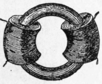
Fig. 1.
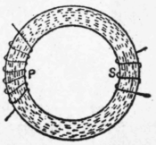
Fig. 2.
A transformer, then may be defined as a device which operates so as to produce instantaneously and directly an increase or decrease of current strength at an expense of a change in the voltage. In many respects a transformer is analogous to the hydraulic press, and is an appliance which does for electrical energy what a system of levers and pulleys does for mechanical energy.
In its simplest form a transformer takes the shape of an annular ring of soft iron wire, upon which the primary and secondary coils are wound. For the purpose of explaining the action of a transformer, we shall consider Faraday's first induction coil, which consisted of a solid iron ring, 7/8" thick and 6" in external diameter, having a primary circuit of wire 72 ft. in length, 1/20" in diameter, and a secondary circuit of wire 60 ft. in length, coiled around the iron core at opposite parts as shown in Figs. 1 and 2, in which P. represents the primary circuit, and S the secondary. The primary circuit was formed of three superposed helices. In each case the wire was bare, each wire being insulated from the next by twine, while the layers were insulated from each other and the core by layers of calico. The three coils on the primary could be used separately or conjointly, in series or in parallel. The dotted circles in Fig. 2 represent the lines of magnetic force or magnetic flux which are set up when a current circulates through P. In Faraday's experiments the current through P was made intermittent, with the result that transient induced currents were produced in S. In practice only alternating currents are used in the primary circuit, and alternating currents are produced in the secondary circuit. Thus, if an alternating current, having a frequency of f periods per second, traverses the primary coil P of our primitive transformer (Figs. 1 and 2), it is obvious that an alternating magnetic flux is developed in the iron core, with the result that a periodic magnetic flux pulsates n opposite directions through the circuit S. This threading or linking of S with an alternating magnetic flux fills and empties the secondary coils at rapid rate, and, according to the laws of electro-magnetic induction, it is clear that an alternating electromotive force, having the same frequency as the primary current supplied, will be induced in S. Furthermore, if the ends of the secondary coil be connected by lamps or wire, an alternating current will traverse this circuit. We thus see that part of the electrical power expended in the primary circuit is recovered in the secondary circuit, and the sources of loss, as we shall presently show, account for the remaining 4 or 5 per cent, of the power expended. As is well known, the inductive action upon which transformers depend exists only while the primary current varies.
At this point it is important to notice that the function of the iron is twofold. (1) It augments the number of lines of force due to the primary current; and (2) it plays the part of a carrier, or forms a suitable medium for the magnetic flux. Consequently, the same result would be produced without the iron core, by placing the secondary coil relatively to P, so that the flux due to the primary current in P, assuming it to be of the same magnitude as when the iron is present, threads itself, and links itself with the coils forming the secondary circuit. It is therefore evident that the E. M. F. is induced in the secondary depends upon, and is a measure of, the mutual induction between the two circuits P and S. In many respects the production of this secondary E. M. F. may be compared to the production of the E. M. F. in the armature of dynamo, although there is no revolving mechanism or moving parts in a transformer. It is also an advantage that transformers need no commutator. The action of the primary circuit is identical with the field coil of a dynamo, whilst the secondary circuit corresponds to the armature coils. In each case relative movement between a magnetic flux and a coil of wire yields induced E. M. F.'s, which in both instances are proportional to the number of turns of wire forming the secondary circuit. In the case of the transformer the nature of the current in the primary circuit P produces the variation in the number of leakages of the lines of force with the secondary circuit S.
Continue to:


My Books

