


Telephone Circuits And Wiring. VIII. Central Energy Systems
Description
This section is from the book "Amateur Work Magazine Vol4". Also available from Amazon: Amateur Work.
Telephone Circuits And Wiring. VIII. Central Energy Systems
ARTHUR H. BELL
One of the great difficulties with magneto circuits when telephone instruments are in constant use, is the exhaustion of the battery supply at each instrument. To improve these conditions telephone electricians sought means of centraliz-izing the batteries at one point, and systems so designed bear the name of "common battery" or "central energy " systems.
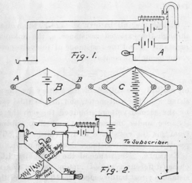
Inumerable circuits have been designed within the past dozen years to simplify the central office equipment, and the method of the "light" system, by which the operator is signalled visually by means of a small incandescent lamp, when the subscriber removes the telephone receiver from the hook, may properly be considered at this time.
The ordinary electric doorbell circuit, comprising a bell, a battery, a push button and some wire, is familiar to all. Let us presume that the doorbell is at the central office with the battery connected to it, and the push button is at the subscribers' station. The bell wire and the telephone button are analogous. By touching the push button the signal is given at central. But supposing the station is a long distance from central. Then the battery current traversing the wires will not be sufficiently strong to ring the bell.
Here enters the relay. Telephone relays act similar to telegraph relays, although their design is different. We all remember how a very feeble current reaches the relay and, after coursing the many turns on the electro-magnet, so energizes the magnet that the armature is attracted to it and thus a local circuit is caused to operate. Let us substitute a relay for the doorbell, and also bear in mind that the subscriber's receiver off the hook acts the same as a depressed push button. With the receiver off the hook the relay at central operates, and at once the local circuit, comprising battery, wiring and a miniature electric lamp, is operated. This attracts the operator's attention, because the lamps are in rows on the front of the switchboard near the "jacks" into which she "plugs in " when answering calls.
The subscriber's instrument is thus simplified by the removal of the ever-falling drops, which had to be restored by hand in many instances. Now, when the subscriber hangs up his receiver the relay armature is released, and the local lamp circuit is opened. This is clearly shown by diagram A, Fig. 1.
Referring to diagram B, Fig. 1, which can be best understood by actual experiment, we find that in a circuit so arranged A cannot talk with B, but if we insert another telephone at C in series with the battery, C will hear A or B nicely, and A will be able to converse in a fairly satisfactory manner with B. The reason for this is, that the construction of the receiver, with its iron core and turns of wire, permits its use as an im-pedence coil, by which the pulsation of the transmitted current are impeded or choked off the battery, as they endeavor to return via the battery supply, while the strength of direct current is reduced only by the resistance of the circuit through which it passes. Telephone electricians, therefore, use the impedence coil in its many forms to utilize one set of batteries, as outlined in diagram C, Fig. 1. To thoroughly understand these circuits the reader should experiment with them. Fig. 2 represents a more complete line circuit. It will be noticed that the jack has two inside contacts which are opened off from the springs when the plug is inserted. This operation removes the line relay and lamp circuit from the line, for the battery for talking is derived from the battery always to be found on common battery switch board cords. When the subscribers are talking the miniature relays in the cord circuit are operated, and thus the lamps' glow assist the operator in watching ber subscribers as they finish conversing and hang up their receivers. This circuit will bear considerable study.
At the subscriber's station the magneto bell is often bridged across the line with a condenser in series, to keep the direct current from the exchange line relay circuit from completing a circuit and keeping the lamp lighted, and sometimes the bell is bridged between one side of the line to the ground, in which case the central operator rings with one side of her plug grounded when signalling the subscriber. In the next chapter will be given a number of diagrams, with brief explanation of each, by which any amateur possessing a few telephone parts may make apparatus suitable for practical and experimental use.
Continue to:


My Books

